
Based LMD18245 bipolar stepper motor control circuit diagram
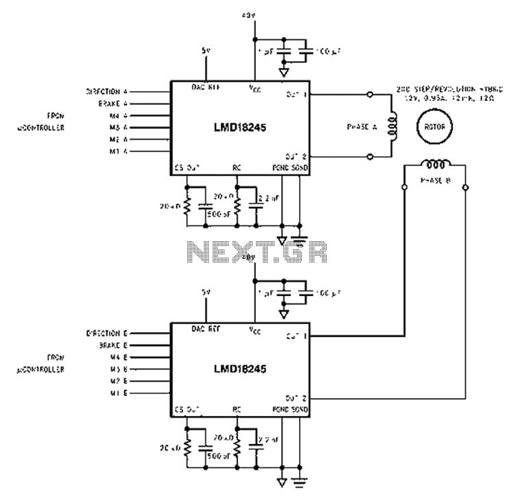
The LMD18245 integrated circuit is designed to efficiently manage motor control applications by utilizing advanced techniques to minimize power loss and optimize performance. The implementation of a fixed off-time chopper strategy allows for precise control of the motor current, ensuring that the motor operates within its specified parameters. The choice of a 20 kΩ resistor in conjunction with a 2.2 nF capacitor is critical for establishing the timing characteristics of the chopper operation, directly influencing the off-time duration and, consequently, the motor's performance.
The capability of the LMD18245 to support both DC brush motors and bipolar stepper motors broadens its application range, making it suitable for various automation and robotics projects. The integration of a DMOS H-bridge power stage not only enhances the output current capacity but also improves thermal management, as the low RDS(ON) reduces power dissipation during operation.
Furthermore, the internal body diode of the DMOS structure simplifies the design by removing the need for additional discrete components, which can complicate the circuit layout and increase the overall size of the motor driver. The digital control aspect, facilitated by the 4-digit DAC, allows for seamless integration with microcontrollers or digital signal processors, enabling sophisticated control algorithms that can adapt to different operational modes such as full step, half step, and micro-stepping.
In conclusion, the LMD18245 bipolar chopper drive stepper motor power stage represents a significant advancement in motor control technology, combining efficiency, flexibility, and ease of use in a compact solution suitable for a broad range of applications.An innovative current detection method, eliminating the power loss of the sense resistor in series with the motor, a 4-digit - analog converter (DAC), provides a digital contro l motor current path, and, by extension, to simplify the implementation of full, half and micro step motor driver, which LMD18245 the application circuit is a bipolar chopper drive stepper motor power stage. 20k resistor and 2.2 nF capacitor connected between the RC and set off time of about 48 microseconds, 20k resistor connected to the output and ground about 200 milliamperes per volt threshold is set to gain in the chopper CS.
Use LMD18245 full-bridge power amplifier integrated DC brush motor bipolar stepper motor or a stage, all of the circuit can be designed to block the application of a variety of motor control and current drive needed. LMD18245 motor control current through a fixed off-time chopper technique, all DMOS H-bridge power stage delivers up to 3A of continuous output current (6A peak) at supply voltages up to 55V DMOS power switch is an efficient low RDS ( ON), and a diode internal DMOS body structure, eliminating the typically required discrete diode clamp bipolar power stage.
An innovative current detection method, eliminating the power loss of the sense resistor in series with the motor, a 4-digit - analog converter (DAC), provides a digital control motor current path, and, by extension, to simplify the implementation of full, half and micro step motor driver application circuit LMD18245 this is a bipolar chopper drive stepper motor power stage. 20k resistor and 2.2 nF capacitor connected between the RC and set off time of about 48 microseconds, 20k resistor connected to the output and ground about 200 milliamperes per volt threshold is set to gain in the chopper CS.
Direction for digital signal control chopped threshold, winding current, by extension, drive type (full step, half step, and so on). Or a digital processor controller usually provide control signals.
Related Circuits
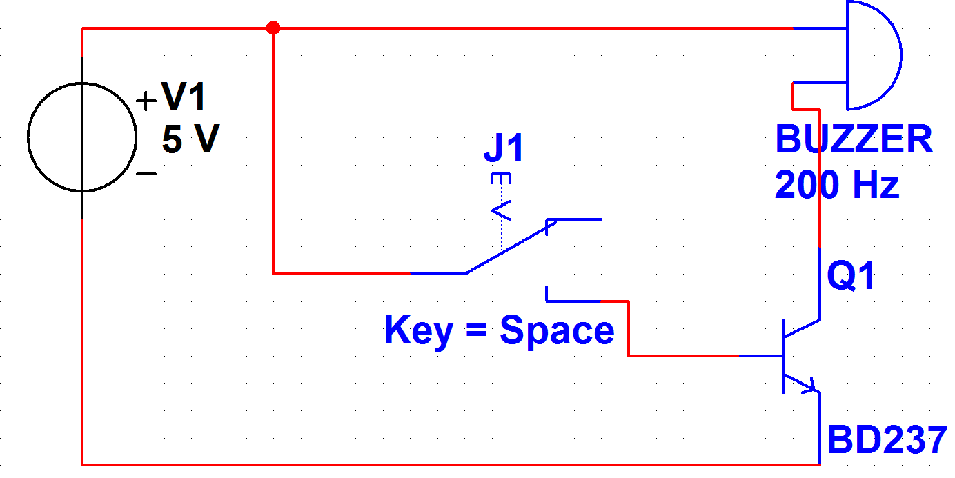
A PB-12N23PW-05Q buzzer is being used with an ATmega 162 microcontroller. Direct connection to the microcontroller pin is not feasible due to the maximum sourcing capability of 20 mA as stated in the ATmega 162 datasheet, while the buzzer...
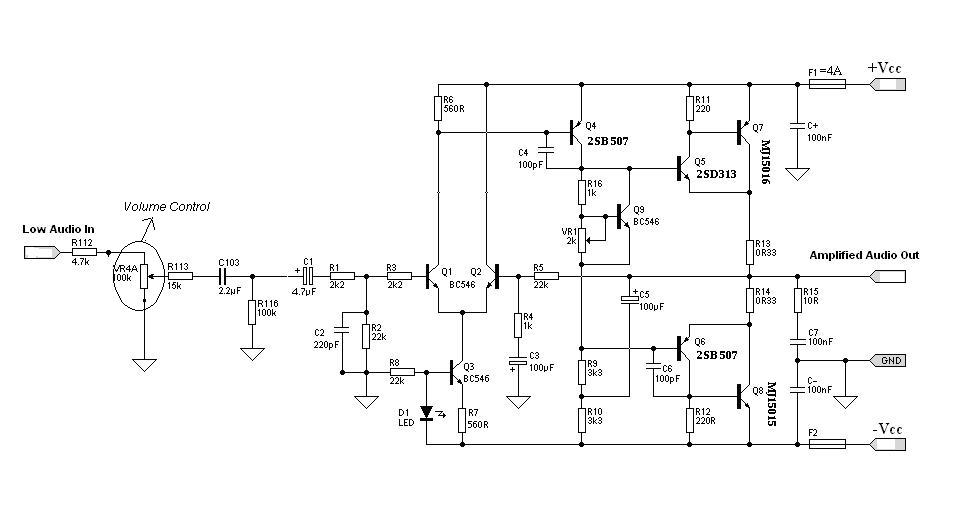
Designing an audio amplifier from scratch using discrete components is an engaging task, as it enables users to create amplifiers that meet diverse requirements. Audio amplifiers can enhance low-level sounds from mobile devices, making them louder and more vibrant....
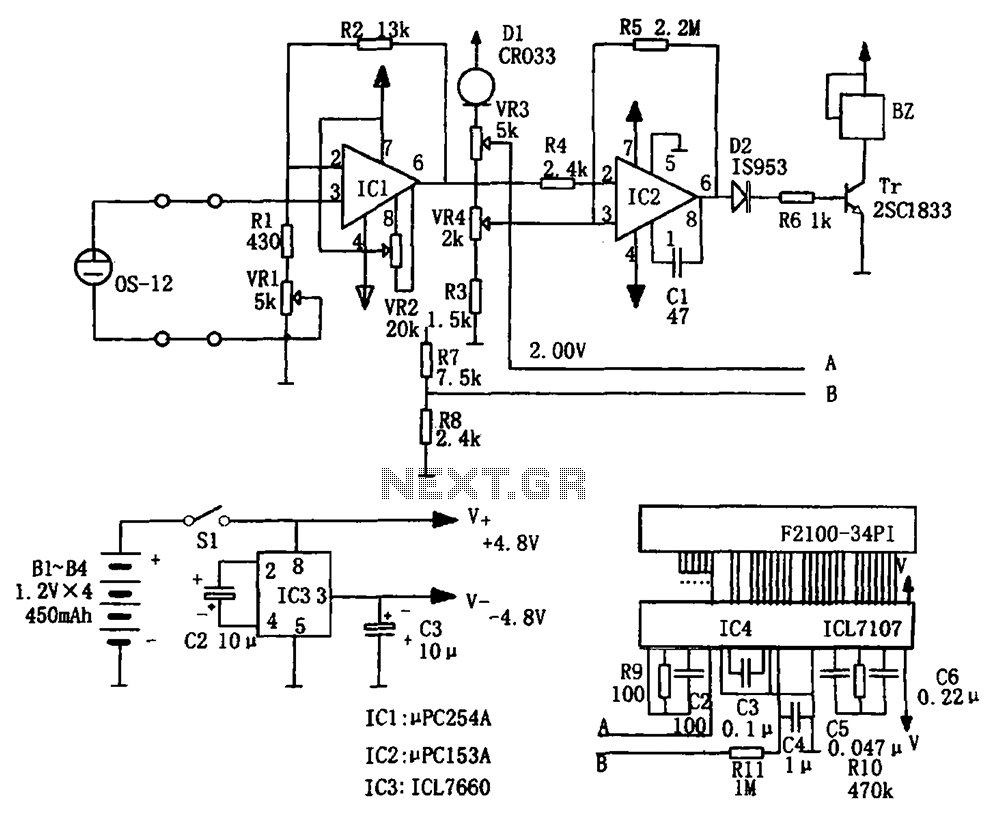
The portable hypoxia monitoring circuit comprises the oxygen sensor OS-12, a DC amplifier IC1, an A/D converter IC4, and a liquid crystal display F2100-34PI. Additionally, it includes a voltage comparator IC2 and a positive and negative power converter IC,...
The Dremel drill fitted with a mini drill-chuck on a stand is a great setup for drilling circuit boards. The problem is that it does not do low speeds very well. My unit had a failed internal speed controller,...
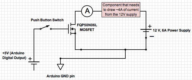
If the ground of the Arduino is disconnected from the negative terminal of the power supply, current flows through the MOSFET, even when the switch is not closed. In an electronic circuit involving an Arduino and a MOSFET, maintaining a...
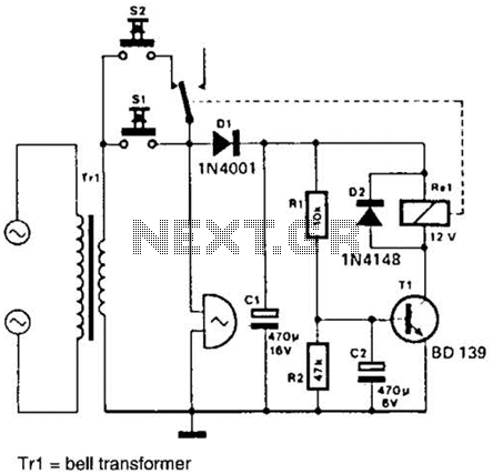
It is often desirable for a single doorbell to be operated by two buttons, for instance, one at the front door and the other at the back door. The additional button, S2 in series with the break contact of...
Warning: include(partials/cookie-banner.php): Failed to open stream: Permission denied in /var/www/html/nextgr/view-circuit.php on line 713
Warning: include(): Failed opening 'partials/cookie-banner.php' for inclusion (include_path='.:/usr/share/php') in /var/www/html/nextgr/view-circuit.php on line 713