
Car Exhaust Meter
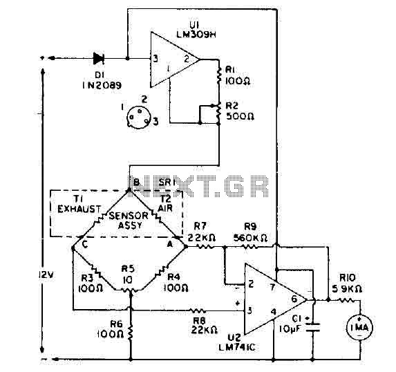
The circuit includes additional components such as a 1 µF electrolytic capacitor rated for 25 volts, a silicon diode (D1) or equivalent (IN2069), and an ammeter (Ml) rated at 0.1 RNA. Resistors R1, R3, R4 are rated at 5 ohms with a tolerance of 10% and a power rating of 0.5 watts. The potentiometer (H2) is rated at 10 ohms, while R5 is a 1-ohm potentiometer mounted on the panel. Additional resistors include R8 rated at 22,000 ohms, R9 at 570,000 ohms, and RL0 at 0.900 ohms. The thermistor sensor (SR1) is part number 1648 from Heath Company. Voltage regulation is managed by an LM309H integrated circuit (U1), and an LM741TC operational amplifier (U2) is used in the circuit. Miscellaneous components include a printed circuit board, screws, a cabinet, welding materials, and 10 feet of plastic tubing.
The bridge circuit is designed to detect minute changes in temperature due to variations in CO concentration in the exhaust compared to the clean air environment. The thermistors operate based on their negative temperature coefficient, where their resistance decreases with an increase in temperature. This characteristic allows for precise measurement and differentiation between the thermal responses of T1 and T2, enabling accurate readings of the CO levels. The differential amplifier enhances the voltage difference generated by the imbalance in the bridge circuit, making it possible to read the output more effectively on the control panel. The calibration process ensures that the readings are accurate and reliable, establishing a baseline when both thermistors are subjected to the same environmental conditions. This circuit can serve applications in automotive diagnostics and emissions testing, providing critical data for compliance with environmental regulations.Bridge circuit contains two resistors lOO-ohm (R3 and R4), and two thermistors (Tl and T2). At room temperature, the resistance of T1 and 1'2 is about 2000 ohms. When they are each heated to 150 ° C by an RNA 10 current, the resistance value decreases to 100 ohms. So. the four elements include a bridge circuit. CO is a characteristic that conducts heat from a thermistor at a rate different from that of air. A thermistor, TI, is exposed to automobile exhaust, while the other, 1'2, is isolated in an environment of clean air.
Unlike thermal conduction bridge imbalance. A voltage difference is caused between points A and C. A differential amplifier. VI, amplifies this difference and leads to the counter with a current sufficient to read the percentage of CO and air-fuel ratio. A control panel before the balance, R5, balances the bridge and calibrates the instrument. The calibration is performed when both thermistors are exposed to outside air. Cl O-1 uF. Electrolytic capacitor 25 vall diode Dl-silicon, general purpose, or equivalent IN2069 Ml-0.1 RNA ammeter Rl. R3, R4, IS-ohm Lao Si 10%. watt resistor Tor! All resistors are 10%, though. SO0 watll H2-ohm potentiometer, PC mounting potentiometer R5-la-ohm, mounting panel Tront H7, R8-22, OOO ohms resistance R9-570, OOO-resistance Ohrn TAB BOOKS, INC.
Fig. 7-3 RL0 S-0.900-ohm resistance thermistor sensor-SR1, num ber 100 Part 1648 of the heat mode hKit HERE ) 080. Heath Company Benton Harbor, MI, 49022 lM309H Ul-S-volt regulator integrated cir- cooked U2-lM741TC op amp circuit intergraled Misc.-PC board, screws, cabinet, welding, hard sections, plastic tubing 10 feet, etc.
🔗 External reference
Related Circuits
A method for determining altitude involves the use of barometric pressure; however, it presents certain challenges. The relationship between pressure and altitude is not linear but rather complex, a concept developed by the army in the 1930s. The equation...
This inductance meter serves as an adapter for a digital voltmeter (DVM), enabling the voltmeter to measure the value of inductors. The inductance meter is particularly useful in designing switch mode power supplies, as it often requires hand-winding coils...
This simple circuit makes it possible to monitor the charging process to a higher level. Final adjustments are simple and the only thing needed is a digital voltmeter for the necessary accuracy. Connect an input voltage of 12.65 volts...

Below is a comparator circuit that can measure the voltage of a car battery in steps of 1 volt. The voltage indication is achieved through comparison. The comparator circuit designed for measuring the voltage of a car battery utilizes an...
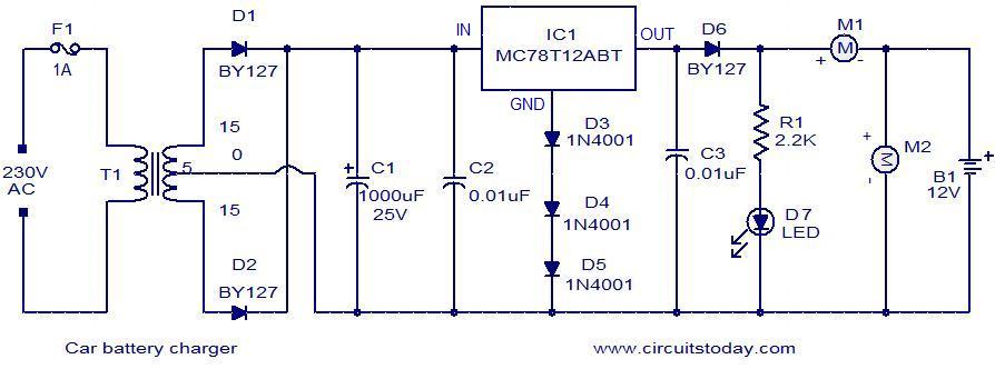
Below is a simple circuit designed for charging car batteries. This circuit includes the capability to monitor both the charging current and voltage. It utilizes the IC MC78T12ABT from Freescale, which is essentially a 7812 in a TO-3 package...
The 555 timer on the right is configured as an alarm sound generator, while the second 555 timer on the left functions as a 1 Hz astable multivibrator. The output from the left timer modulates the frequency of the...