
Voltmeter With LED For Car Battery
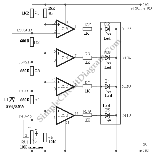
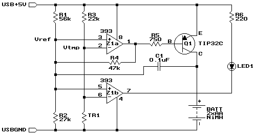
The comparator circuit designed for measuring the voltage of a car battery utilizes an operational amplifier (op-amp) configured as a comparator. This circuit provides a simple yet effective means to monitor the battery voltage, ensuring that the vehicle's electrical system operates within safe parameters.
The circuit typically consists of an op-amp, a reference voltage divider, and an output indicator, such as an LED or a digital display. The reference voltage is set using resistors to create a series of voltage levels corresponding to the desired measurement increments (1 volt in this case). The car battery voltage is connected to the non-inverting input of the op-amp, while the reference voltage is fed into the inverting input.
As the battery voltage varies, the op-amp compares the input voltage from the battery against the reference voltage. When the battery voltage exceeds the reference level, the output of the op-amp switches states, activating the output indicator. This provides a visual representation of the battery voltage level. By designing multiple reference levels, the circuit can indicate different voltage ranges, allowing for a clear understanding of the battery's status.
For enhanced functionality, the circuit may include additional components such as hysteresis to prevent rapid switching of the output near the reference voltage thresholds, or a microcontroller for digital signal processing and more precise readings. This comparator circuit serves as a vital tool for monitoring car battery health and ensuring reliable vehicle operation.Below is a comparator circuit which is can measure with step of 1 volt, the voltage of car battery. The indication of voltage is done by comparison of .. 🔗 External reference
Related Circuits

The UC3906 battery charger circuit controller includes all necessary circuitry to manage the charge and hold cycles for sealed lead-acid batteries. This circuit is specifically designed to deliver the appropriate charging voltage and current based on the battery's temperature...
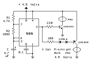
The 555 circuit below is a flashing bicycle light powered with three C or D cells (4.5 volts). The two flashlight lamps will alternately flash at an approximate 1.5 second cycle rate. Using a 4.7K resistor for R1 and...
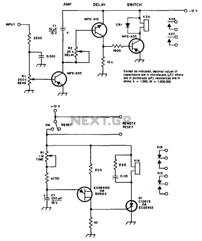
A circuit diagram illustrates a COR/CAS circuit designed for repeater applications. CR1 is identified as a silicon diode, while relay 2 can be any relay with a 12-V coil, with a reed relay being preferred for longevity. Resistor R2...
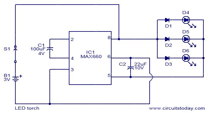
This is a simple LED torch circuit based on the MAX660 integrated circuit from MAXIM semiconductors. The MAX660 is a CMOS monolithic voltage converter IC capable of driving three bright white LEDs connected in parallel to output pin 8....
It may be necessary to use 10 diodes and various resistors, particularly when utilizing white LEDs. Refer to the Troubleshooting section in step 3 for more details. A sheet of 0.005-inch thick matte drafting film was purchased from a...
Widely available AA NiMH battery chargers are on the market, including those packaged to charge various battery types such as NiCd and NiCad. This project features a battery charger designed for two AA NiMH or NiCd cells of any...