
Car Light Dimmer 12 Volt
The circuit described is a dimming control for a dome light in an automotive application, leveraging a capacitor and an operational amplifier (op-amp) to create a gradual fade-out effect. The primary components involved in this circuit include a 22µF capacitor, an operational amplifier (specifically an IC 741), a transistor, a variable resistor (VR1), and a fixed resistor (10KΩ).
When the car door is opened, the push-to-off switch is activated, allowing the capacitor to charge to the supply voltage of 12V. The op-amp, configured as a voltage follower, ensures that the output voltage mirrors the voltage across the capacitor. This high output voltage saturates the transistor, which in turn drives the dome light to full brightness.
Upon closing the door, the switch is disengaged, and the capacitor begins to discharge through the variable resistor VR1 and the 10KΩ resistor. The discharging process results in a gradual decrease in voltage across the capacitor. Consequently, the output voltage from the op-amp also decreases, which reduces the base current to the transistor. This reduction in current results in a corresponding decrease in the brightness of the dome light, creating a smooth fade-out effect.
The circuit allows for adjustable settings via the variable resistors. VR2 is utilized to set the initial brightness of the dome light when the door is open, while VR1 controls the discharge rate of the capacitor, thereby adjusting the time it takes for the light to fade out completely after the door is closed. It is recommended to set both VR1 and VR2 to their maximum values initially to observe the full range of functionality before making precise adjustments.
Overall, this circuit enhances the aesthetic experience of the vehicle's interior lighting, providing a gradual transition that can contribute to a more pleasant ambiance during nighttime use.This unique circuit makes your dome light look cool. Usually when the car door is closed, the dome light just goes OFF. With this circuit, you can have our dome light fade slowly in brightness and finally go OFF. This slow dimming of the light gives a very good feeling at night. It looks very romantic! The circuit can be explained as follows: When the car door is open, the push to off switch of the door is ON and hence it charges the 22uF capacitor fully. The opamp is acting as a voltage follower and its output is same as the voltage across the capacitor, which is 12V when the capacitor is fully charged.
Due to a high voltage at the output of the IC, the transistor saturates, turning ON the bulb to full brightness. Now when the door is closed, the door switch is pushed in and hence the switch goes OFF. When the switch is OFF, the capacitor starts discharging slowly through VR1 and the 10K resistor and the voltage across it decreases slowly. Hence at the output of IC 741 also the voltage decreases gradually, hence decreasing the base current to the transistor.
This produces a slowly decreasing current through the bulb and the bulb fades out and finally when the capacitor is fully discharged, the bulb goes OFF. After building the circuit, with the push-to-off switch in ON position (not pushed in) i.e. the car door open, adjust the preset VR2 to the required initial brightness of the bulb. Then push the switch in to turn it OFF(or close the door) and adjust VR1 for the time to bring the bulb from full brightness to OFF.
I would suggest you set VR1 and VR2 to their maximum values. 🔗 External reference
Related Circuits
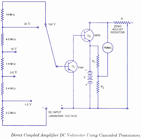
This type of voltmeter is very common due to its low cost. It is designed to measure voltages in the milli-volt range because of limited amplifier gain. The circuit diagram for a direct-coupled amplifier DC voltmeter using cascaded transistors...
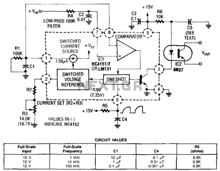
In this circuit, a Raytheon RC4151 or National LM131 is utilized alongside an optocoupler for applications where input-to-output isolation is desirable. Circuit values are indicated in the figure for various applications. The circuit employs a Raytheon RC4151 or National LM131,...
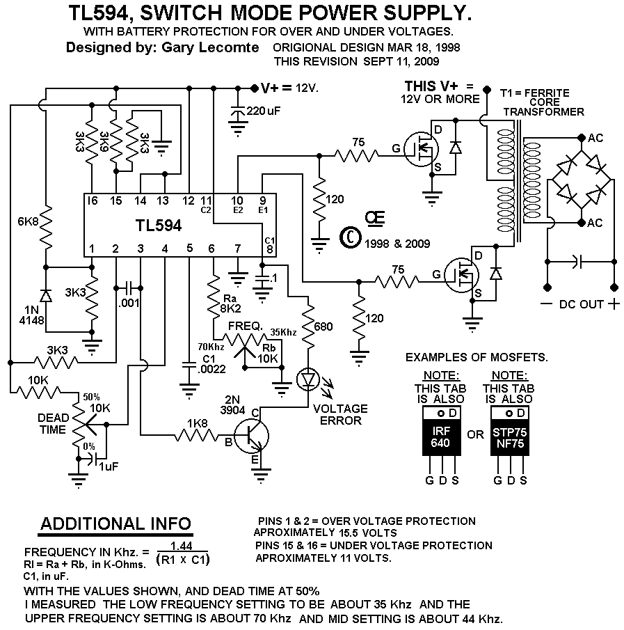
This circuit is designed for individuals needing to boost or drop a voltage. The output operates at high frequency but can be rectified and filtered to provide a DC output. When rectifying high frequencies, it is essential to utilize...
A general-purpose hobby circuit for a simple light fence security beeper is presented here. This circuit can be utilized as a door alarm, gate alarm, pathway alarm, and more. It can be powered by any 12 Volt DC power...
This is an improved version of the audio interface commonly used to connect a computer soundcard to a transceiver's receive and transmit audio circuits. This kind of interface is used by computer programs that send and receive SSTV, RTTY,...

This application note discusses the use of SEPIC power modules to supply the necessary power for driving high-brightness LED arrays. These arrays serve as display backlights and necessitate a wide dimming range. The SEPIC configuration offers an efficient and...