
Voltage-To-Frequency Converter With Optocoupler

The circuit employs a Raytheon RC4151 or National LM131, both of which are precision voltage references known for their stability and low drift characteristics. These components are integrated with an optocoupler to ensure electrical isolation between the input and output, which is crucial in preventing ground loops and protecting sensitive components from voltage spikes or noise that may be present in the input signal.
The optocoupler serves as a crucial interface that transmits signals while maintaining isolation. It typically consists of a light-emitting diode (LED) and a photodetector, such as a photodiode or phototransistor, housed within a single package. When an input voltage is applied to the LED, it emits light, which is detected by the photodetector on the output side, thus transferring the signal without a direct electrical connection.
The circuit values, which are specified in the accompanying figure, can vary depending on the specific application requirements, such as the desired input and output voltage levels, current ratings, and response times. These parameters must be carefully selected to optimize the performance of the circuit while ensuring reliable operation under varying conditions.
In applications where isolation is paramount, such as in industrial control systems, medical devices, or communication equipment, this configuration provides an effective solution. It allows for the safe transmission of signals across different voltage domains, ensuring that the integrity of the sensitive output circuitry is maintained. In this circuit, a Raytheon RC4151 or National LM131 is used in conjunction with an optocou pler for applications where input-to-output isolation is desirable. Circuit values are shown in the figure for various applications.
Related Circuits

Symmetric 12V to 5V converter power supply. Refer to the designated page for an explanation regarding the associated circuit diagram. The symmetric 12V to 5V converter power supply is designed to efficiently step down a 12V input voltage to a...
The circuit diagram illustrates two LT1398 operational amplifiers from Linear Technology utilized to generate buffered color-difference signals from RGB (red-green-blue) inputs. In this setup, the R input is received through a 75-ohm coaxial cable and directed to the non-inverting...
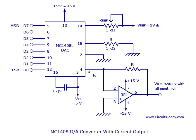
Monolithic/Hybrid Digital to Analog Converters using MC 1408 IC, SE/NE 5018, Specifications and Applications. Monolithic and hybrid digital-to-analog converters (DACs) are integral components in various electronic systems, facilitating the conversion of digital signals into corresponding analog voltages or currents. The...
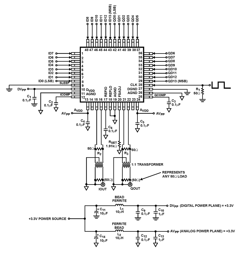
The ISL5929 is a dual 14-bit, 130/210+ MSPS (Mega Samples Per Second), CMOS, high-speed, low-power, digital-to-analog converter (DAC) designed specifically for high-performance communication systems, such as base transceiver stations utilizing 2.5G or 3G cellular protocols. The ISL5929 DAC is engineered...
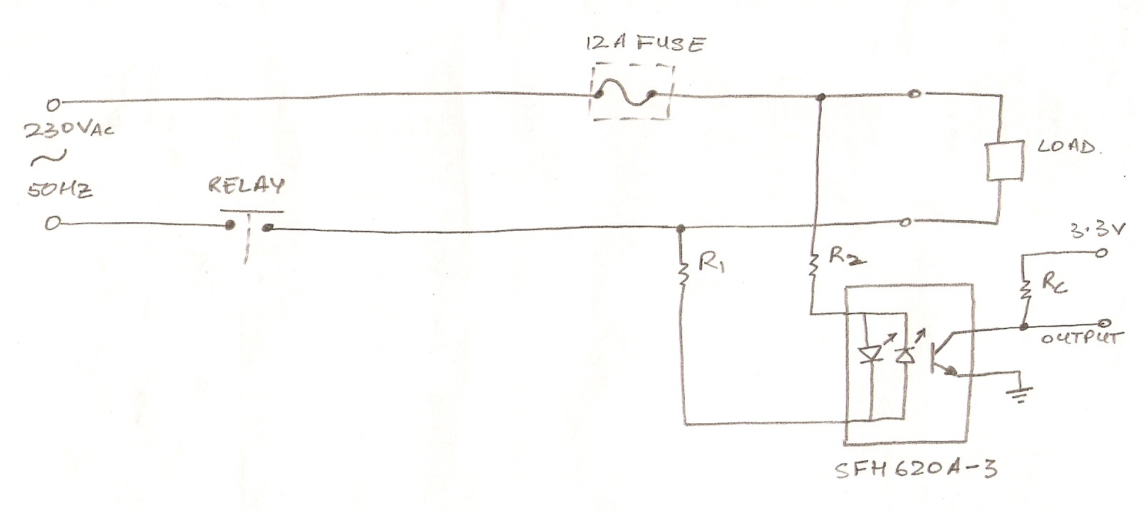
The circuit utilizes an optocoupler (MOC3021) to detect the On/Off state of an electrical appliance using a microcontroller (ATmega16L). The mains supply specifications are 230V, 50Hz. The design aims to determine whether the load is active or inactive. The...
Build an interface board to connect scientific equipment, specifically a pair of photovoltaic tubes, to a personal computer for acquiring measurement results. The signal properties include two channels with a common ground, a one-second acquisition time, and a maximum...