
Car maintenance thyristor voltage regulator

The JFYJ2102 type AC permanent magnet generator operates by converting mechanical energy into electrical energy using permanent magnets. The generator's output is three-phase AC, which is then rectified using a three-phase bridge rectifier composed of thyristors. The thyristors are controlled through a triggering mechanism that ensures they conduct at the appropriate times, allowing for efficient power conversion and regulation.
The voltage regulation process is critical for maintaining a stable output voltage, particularly in automotive applications where fluctuations can affect performance and safety. The use of zener diodes in the circuit provides a voltage reference, ensuring that the system responds correctly to changes in load and input conditions. The isolation diodes prevent backfeeding into the generator, which could lead to damage or malfunction.
The design of the circuit includes careful consideration of component ratings and specifications to ensure reliability and longevity. The use of metal film resistors and appropriate transformer materials minimizes losses and enhances the overall efficiency of the system. The winding ratios of the isolation transformer are chosen to optimize the trigger pulse characteristics, ensuring that the thyristors are activated at the right moments.
In practical applications, the installation of the regulator circuit board should be performed with attention to environmental factors, such as moisture and dust, which can compromise the integrity of the components. Sealing the board with silicone rubber provides a protective barrier, extending the lifespan of the regulator in automotive environments.
Overall, the design and implementation of the JFYJ2102 generator and its associated voltage regulator circuit exemplify advanced engineering principles in power electronics, focusing on reliability, efficiency, and adaptability to various operational conditions.An automobile permanent magnet alternator failure, the phenomenon of cars at night driving, headlights suddenly increase in brightness, then goes out. Analyzing the generator v oltage regulator may be damaged, resulting in the voltage rise due. This generator has no part excitation coil can not use a conventional voltage regulator substitution. This machine is JFYJ2102 type (28V/36A) AC permanent magnet generator, higher power, better use. Aircraft trigger regulator circuit board has been lost, as shown by the actual mapping generator wiring diagram in Fig.
The circuit is a three-phase bridge rectifier semi-controlled thyristor surge line, G for the three-way thyristor trigger pole, and at the same time is triggered, D7, D8, D9, respectively, for the three SCR KGZ1, KGZ2, KGZ3 trigger extreme isolation diode, C1, C2, C3 is to prevent interference with pulse thyristor three false triggering while protecting three pole SCR trigger, the breakdown will not be too high and high voltage pulse, play a protective role; D4, D5, D6 of isolation diode to prevent the three SCR cathode is directly connected, and the resulting three-phase winding of the generator is short-circuited in order to give the three thyristor cathode electrode is applied to the trigger and the trigger pulse. Synchronous detection control circuit and transistor relaxation oscillator circuit consists of BG this single-junction transistor BT composition than the composition.
When the B + on the termination power, through the current limiting resistor R6 and zener diode ZD2 to the oscillator power supply via a resistor R2 to the capacitor C1 is charged, when the voltage rises across the single-junction transistor G1 peak voltage of BT, BTs e, b1 extremely conductive, capacitor C1 by BT of e, the primary L1 b1 pole isolation transformer to discharge. When the voltage of C1 drops to the valley point BT, BTs e, b1 extremely restore blocked. Then began the second capacitor C1 charge/discharge, so the cycle. After the start-up circuit, through the isolation transformer B L2 of the output pulse, the G, A is added to the end of the SCR triggered thyristor pole leaving.
Since the power from the three-phase rectifier pulsating power, so the output pulse in synchronization with the pulsating power thyristor can be synchronized trigger. When the B + terminal voltage reaches or ZD1 breakdown conduction, BG base potential rises above 28V, BG conduction, the collector potential decreases, the diode D2 is turned on, so that a short circuit across C1, the oscillator to stop, SCR not the trigger signal, the zero crossing is blocked.
When the voltage is below 28V, ZD1 breakdown is not, BG group is extremely low potential, BG off, its collector is high potential, D2 off, oscillator, SCR is triggered by conduction, the rectifier output current outward powered by. So again and again, always the rectifier output voltage of the generator does not exceed 28V. If the trigger current is too small, it can be appropriate to reduce the resistance R in Figure 1. Selection of all the circuit resistance metal film resistors 1/2W A, B selected magnetic tank or cross-sectional area of 0.5 to 0.8c©O S25mm radio transformer core with S0.23 ~ S0.25mm enameled wire, L1 about 100T, L2 around 200T.
Power LD light bulbs, power supply with adjustable output voltage rises when output is 28V, the lamp LD suddenly extinguished; when the voltage is set lower than 28V, the lamp can be lit again LD, otherwise, it should change the value ZD1, R4s. Then trigger the regulator circuit board connected to the corresponding connection generator mounted to the car test run, if stable, to the board with silicone rubber seal to prevent water and dust.
This triggers the regulator by the actual use of good results, this method can be a similar type of generator maintenance; if it is 14V generator can change values of R, ZD1, so just ZD1 is turned on when the 14V far; at the same time to R6 100, ZD2 to 10V zener diode. Car repair thyristor circuit diagram of the voltage regulator shown in FIG.
Related Circuits
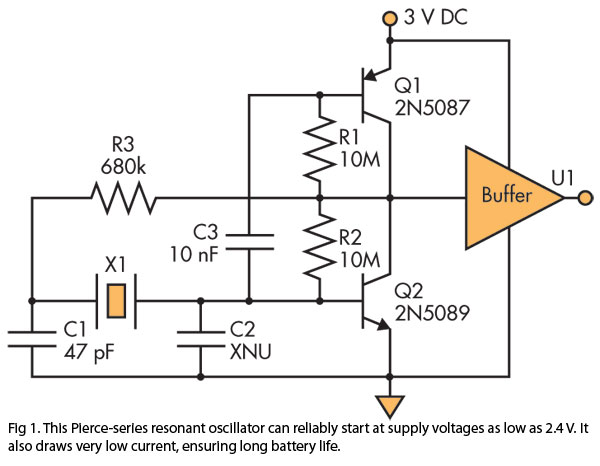
A Pierce (crystal) oscillator designed to deliver a stable clock signal for a minimum duration of one year when powered by battery voltages as low as 2.4 V. The Pierce oscillator circuit is a type of crystal oscillator that utilizes...
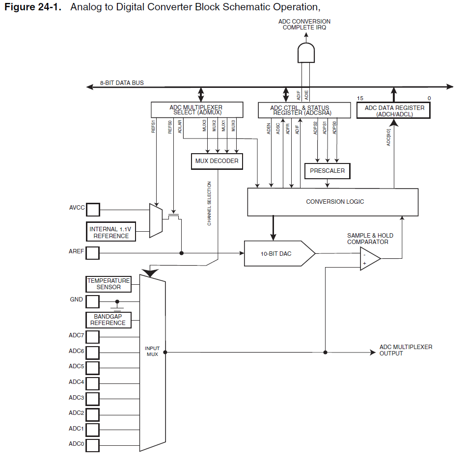
When using the internal 1.1V reference for the ADC, if the analog input exceeds 1.1V, such as 2.5V, it will not harm the microcontroller. Instead, the ADC value will clip at 0x3FF. Based on practical experience, it has been...
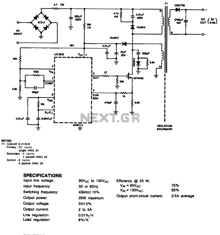
This circuit employs a cost-effective feedback scheme where the direct current voltage generated from the primary-side control winding is monitored by the UC1842 error amplifier. Consequently, load regulation is influenced by the coupling between the secondary and control windings,...
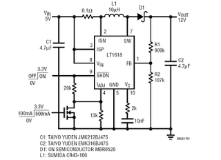
This is a 5V to 12V DC-DC step-up (boost) converter circuit designed specifically for USB-powered applications. A USB port has two current supply modes. Initially, it supplies a maximum of 100mA to the load before detecting the connected device....
The VFC62 is a voltage-to-frequency and frequency-to-voltage converter that effectively transforms analog signals into digital signals. The digital output is presented in an open collector format, where the digital pulse repetition rate is directly proportional to the amplitude of...
The TDA8340Q and TDA8341Q are integrated intermediate frequency (IF) amplifier and demodulator circuits designed for color and black-and-white television receivers. The TDA8340Q is intended for use with NPN tuners, while the TDA8341Q is suitable for PNP tuners. Both components...