
Crystal Oscillator Features Low Current Low Startup Voltage

The Pierce oscillator circuit is a type of crystal oscillator that utilizes a quartz crystal to generate a precise frequency output. It typically consists of an inverter or an operational amplifier configured as a negative resistance amplifier, which is connected to a quartz crystal. The crystal acts as a frequency-selective element that determines the oscillation frequency based on its physical properties.
In this particular design, the oscillator is optimized for low-voltage operation, enabling it to function effectively at battery voltages as low as 2.4 V. This is particularly beneficial for portable electronic devices where power efficiency is critical. The circuit is designed to maintain stable oscillation over a prolonged period, ensuring that the clock signal remains reliable for at least one year of continuous operation.
Key components of the Pierce oscillator include a feedback network formed by the crystal, which provides the necessary phase shift and gain for oscillation. The inverter or operational amplifier used in the circuit must have a low supply voltage threshold to accommodate the 2.4 V requirement while ensuring sufficient gain to sustain oscillation.
The output of the oscillator can be taken directly from the inverter or amplifier, which can be interfaced with digital logic circuits, microcontrollers, or other timing applications. The design should also consider the inclusion of decoupling capacitors to filter out noise and stabilize the power supply, enhancing the overall performance and reliability of the oscillator.
In summary, the Pierce oscillator described is a compact and efficient solution for generating a consistent clock signal in battery-operated devices, emphasizing longevity and low power consumption without sacrificing performance.A Pierce (crystal) oscillator intended to provide a reliable clock signal for at least 1 year when powered by battery voltages as low as 2.4 V 🔗 External reference
Related Circuits
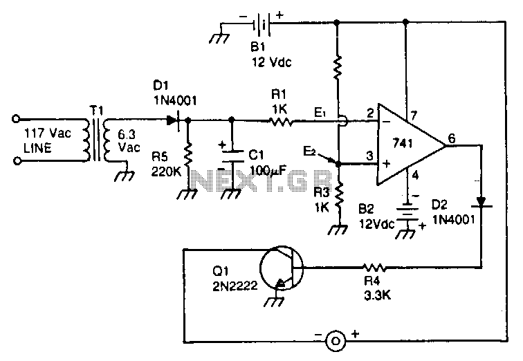
This circuit utilizes a type 741 operational amplifier (op amp) configured as a voltage comparator. One input of the 741 is connected to a reference voltage, sourced from a 12-V battery, via a resistor voltage divider. The voltage at...
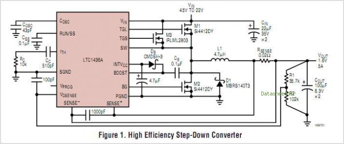
In broadband networking and high-speed computing applications, multiple high-current, low-voltage power supplies are required to power FPGAs, flash memory, DSPs, and microprocessors. One example specifies a maximum current of 60A to power the CPU at 1.5V and up to...
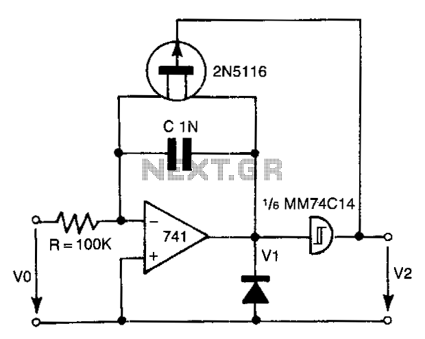
The 741 operational amplifier integrator signal is input into the Schmitt trigger of an inverter. When the signal reaches the positive-going threshold voltage, the inverter's output switches to zero. This output directly controls the FET switch. With a gate...
The current mode amplifier offers the advantage of higher frequency operation, and the LM359 serves as an operational amplifier of this type. The current mode amplifier is designed to operate with input signals in the form of current rather than...
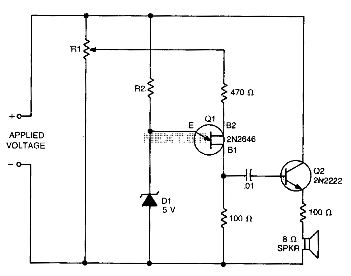
The values of R1, R2, and D1 are selected based on the voltage applied. Using a 12-volt battery, R1 is set to 10 kΩ, R2 to 5 kΩ, and D1 is a 5-volt zener diode or a string of...
The hobby circuit described can be connected to a 3V battery to provide a warning when the battery is nearing its end of life. It will flash an LED when the battery voltage drops to approximately 2.4 volts. The...