
Car rear Stop Light Flasher
The circuit operates by utilizing a combination of resistors, capacitors, and a relay to manage the switching behavior of the third brake light. The primary components include:
- **Resistors (R1 to R5)**: These resistors are used to set the timing and current levels within the circuit. R1 (10 ohms) helps limit the current, while R2 (39k ohms) and R3 (1 Mohm) are involved in the timing circuit. R4 (1 Mohm) and R5 (39k ohms) contribute to the control of the relay and the charging of the capacitors.
- **Capacitors (C1 to C5)**: Capacitors are critical in determining the timing of the ON/OFF switching of the third brake light. C1 (10 nF) and C2 (100 nF) are used for filtering and stability, while C3 (47 µF) serves to hold charge for timing. C4 (0.68 µF - 1 µF) and C5 (3.3 µF) can be adjusted to modify the frequency and duration of the flashing sequence.
- **Integrated Circuit (IC 1)**: The 4093 IC is a quad Schmitt trigger, which is used in this circuit to provide the necessary logic for the ON/OFF switching action of the brake light.
- **Transistor (Q1)**: The BD679 transistor acts as a switch to control the relay, allowing the circuit to handle higher currents necessary for the brake light operation.
- **Diodes (D1-D4)**: The 1N4148 diodes are used for flyback protection across the relay coil, preventing voltage spikes that could damage other components when the relay is switched off.
- **Relay (RL1)**: A 12V DC relay rated for over 10A is used to switch the brake light circuit. The relay allows the low-power signal from the timing circuit to control the higher-power brake light.
- **Connectors (SL1-2)**: M-F connectors are used for easy connections within the circuit, allowing for straightforward assembly and maintenance.
This design ensures that the third brake light provides a clear visual signal to drivers behind, enhancing safety by alerting them when the vehicle is stopping. The adjustable timing feature allows customization based on user preference while maintaining effectiveness in communication with following vehicles.When we step on the car' s brake, then together with the classic rear STOP ,the third STOP which is situated in the middle of the back half of the car also switches ON. This is the classic function , is to be found in all modern cars. The difference with the circuit is that when we "step on the brake " then the third STOP switches ON and OFF rhythmically once a second , three times, it then reverts to it' s normal functioning, remaining constantly switched ON, with the provision that we will continue to " step ON" the brake.
If we leave the brake, the STOP switches off ,waiting useful for drivers who come from behind and are relatively alert their attention, with the result that we avoid a visit from behind, with the corresponding consequences. The switching on and off and the length of time can be adjusted champing the use of the capacitance at C4/ C5, being careful always that they are not too big, because then the switching on/off becomes annoying for the drivers behind. The operation is done carefully cutting off the continuation of feting +12V which leads to the third STOP and intervening in turn the circuit , taking from some near by point of the chassis (0V).
That which must be watched is that the Relay RL1 is of good quality. Part List R1=10ohms C1=10 nf 100V MKT IC 1=4093 R2= 39Kohms C2=100nF 100V MKT Q1=BD679 R3=1Mohms C3=47uF 25V D1-D4=1N4148 R4=1Mohms C4=0.68uF - 1uF 25V RL1=12V DC RELAY 2X2 [>10A] R5= 39Kohms C5=3.3uF 25V SL1-2=M-F CONNECTORS 🔗 External reference
Related Circuits
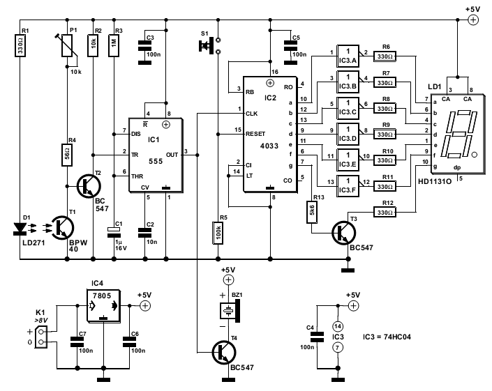
The circuit detailed here counts the number of times an infrared beam is interrupted. It can be utilized to track the number of individuals entering a room or to monitor how frequently an object, such as a ball, passes...
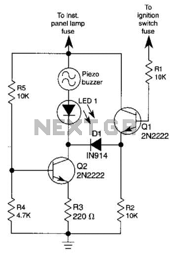
The base of Q1 is connected to the car's ignition circuit; the easiest point to make that connection is at the ignition switch fuse in the car's fuse panel. Also, one side of the piezoelectric buzzer is connected to...

This Project Automatic Room Light Controller with Visitor Counter using Microcontroller is a reliable circuit that takes over the task of controlling the room lights as well as counting the number of persons/visitors in the room very accurately. When...
The circuit shown here is used to switch on a lamp when the telephone rings, if the ambient light is insufficient. The circuit uses only two ICs and it can be implemented very easily. A light dependent resistance (LDR),...
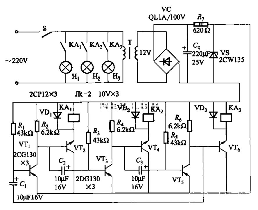
The transistors VTi, VT3, and VTs, along with the RC components, form three distinct multi-resonator oscillators. The oscillation frequency levels are dependent on the values of Ri, R3, Rs, and Cl, as well as Cz and C3s. The circuit comprises...
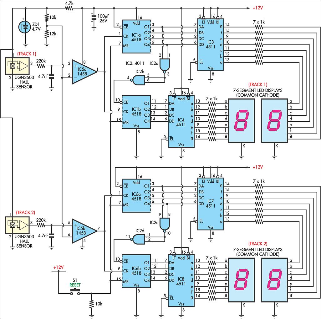
AFX slot car sets are enjoyable, and the experience can be enhanced with a lap counter. This circuit counts from 00 to 99, featuring independent counters for each track. The sensing device utilized is a Hall effect sensor (UGN3503;...