
Car security system design based on PIC microcontroller and GPS tracking
The described anti-theft system is a sophisticated arrangement designed to enhance vehicle security through the integration of multiple components. The dual-frequency sirens act as a deterrent and alert mechanism, while their connection to the vehicle's immobilizer system ensures that unauthorized access is effectively prevented. In the laboratory simulation, the use of LEDs to indicate various operational states provides a clear visual feedback mechanism, allowing for real-time monitoring and diagnostics.
The incorporation of push buttons in place of a traditional security keypad simplifies user interaction, making the system more accessible. The logic level adaptation using the MAX232 IC is crucial for ensuring compatibility between the microcontroller and the GPS module, allowing seamless communication and operation.
The GPS receiver's adherence to the NMEA standard at a baud rate of 4800 bps is essential for reliable data transmission, facilitating accurate tracking and positioning. The high sensitivity and positioning accuracy of the GPS receiver enhance the effectiveness of the anti-theft system, providing real-time location data that can be critical in the event of theft.
The strategic placement of the GPS receiver within the cabin light casing not only secures the device but also ensures uninterrupted power supply and minimal interference with satellite signals. The selection of an electronic siren capable of producing both high and low tones maximizes the auditory alert potential, making the system more effective in deterring potential thieves.
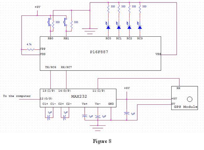
Overall, the design and implementation of this anti-theft system reflect a comprehensive approach to vehicle security, combining advanced technology with practical considerations for installation and maintenance. The system's features and components are meticulously chosen to ensure reliability, functionality, and ease of use, ultimately enhancing the safety and security of the vehicle.The actual anti-theft system is equipped with two frequency siren and connected to a vehicles immobilizer system. But in the laboratory simulation model; the change of operating modes, triggering of the siren and cutting off of the fuel supply to the engine is indicated by lighting of LEDs as well as from the computer through the serial communicat
ion. Instead of the Security key-pad, ON and OFF push buttons are incorporated in the simulation. In micro-controllers, logic 1 and logic 0 correspond to +5V and 0V respectively. But in the GPS module as well as in the computer, the logic 0 and logic 1 correspond to -15V and +15V respectively. Therefore, MAX232 IC has been incorporated to match the logic levels. The GPS receiver uses the NMEA standard with a baud rate of 4800 bps, therefore the serial communication baud rate of the PIC and the PC should also be 4800 bps.
The system should be programmed to read NMEA standard messages. This GPS receiver has a high sensitivity and a reasonable positioning accuracy which is matching to the anti-theft system. The maximum operating temperature of the receiver is +80 °C which is way higher than the maximum temperature that could occur inside the vehicle and since a normal vehicle does not exceed a maximum velocity of 83 m/s and a maximum acceleration 4g, it is ensured that the selected GPS receiver is ideal for the anti-theft system.
It was decided to fix the GPS receiver inside the casing of the cabin light. This location is selected because, it is well secured and it has a continuous power supply. The receiver`s access to the sky will not heavily weaken because of the roof. An electronic vehicle siren with a high and low tone will be used as the warning siren. The selected siren provides the both high and low frequency sirens. The capacity of the battery of the vehicle is adequate for the energy dissipation of the siren; this siren is ideal to be used for the anti-theft system. It has been decided to fix the siren inside the bonnet of the vehicle, as it is easy for repairs and replacements.
🔗 External reference
Related Circuits
A car courtesy light in a standard vehicle without a board computer functions simply: when the door is opened, the interior light turns on, and when the door is closed, the light turns off. For convenience, it is beneficial...
The electric car remote control circuit diagram enables the model car to move forward and backward, as well as turn left and right. It is simple and easy to operate. The radio remote control receiver demodulation circuit utilizes TWH9238...
The primary amplifying stages consist of triode-connected 6088 tubes. As previously mentioned, there are two amplifying stages, which provide a non-inverted input to output connection and sufficient gain to include tone control. The tone controls are switch-selected, allowing a...
An op-amp based Colpitts oscillator in Multisim displays a "timestep too small" error when the run button is pressed. Despite extensive research and attempts to resolve the issue, the error persists. The design features a C-L-C pi circuit that...
Switching to alternative power sources can help reduce electricity bills. The photovoltaic module or solar panel described here is capable of generating renewable energy. The photovoltaic module, commonly known as a solar panel, is a device that converts sunlight into...
Creating projects that connect to the phone line can be a real chore without some device like this. It generates the 48 volts DC for the on-hook condition, the 100 volts AC for the ring signal, and the 20...