
6088 Based Battery Powered Full Feature Preamp Part 3

The circuit employs a dual-stage architecture utilizing triode-connected 6088 tubes, which are known for their favorable linearity and low distortion characteristics. The first stage's slightly starved configuration not only provides the necessary gain but also ensures that the signal remains clean and well-defined before it is processed by the tone control circuits. The tone control section is designed for flexibility, allowing the user to engage a flat response that bypasses reactive components, thus maintaining signal integrity for critical listening applications.
The coupling between the first and second stages is crucial; the gain structure is carefully balanced to achieve an overall gain of approximately 20dB. The output impedance is maintained below 10kΩ, which is advantageous for driving downstream components without significant loading effects. The separate board for the amplifier section facilitates thermal management and reduces noise coupling between stages.
The design incorporates a DC ground path for enhanced stability and reliability, particularly important in audio applications where signal integrity is paramount. The inclusion of additional resistors and capacitors at the input and output stages serves to filter out unwanted noise and ensures a stable DC return, which is especially beneficial when interfacing with various audio sources.
The use of a 6418 as a unity gain buffer in the tape monitor output highlights the design's attention to detail, ensuring that signal integrity is preserved even when the output is routed through additional processing. The unique balance control design, while unconventional, allows for fine-tuning of the audio output, enhancing user experience.
The 6.8pF capacitor plays a critical role in maintaining frequency response, effectively compensating for the inherent capacitance in the circuit. The tone control mechanism, based on variable reactance, offers a sophisticated approach to sound shaping, minimizing unwanted interactions between frequency bands and providing a more musical response.
Overall, this preamp design exemplifies a thoughtful integration of components and circuit topology aimed at achieving high fidelity audio performance while maintaining user-friendly operation and adaptability for various listening preferences.The main amplifying stages are triode connected 6088 stages. As indicated from the previous part, there are two amplifying stages. This provides a non-inverted input to output connection, as well as sufficient gain to incorporate tone control. The tone controls are switch selected so that "flat" bypasses all reactive elements; truely flat response
. The overall circuit topology is again shown here for completeness: Notice that the first stage is slightly starved. This provides a gain of about 9. This drives the tone control and balance circuits that introduce a loss of about 7. 2. The second stage is operated at slightly higher current, and has a lower plate resistor, so that the preamp "output" impedance is less than 10k.
The second stage has a gain of about 8, so the overall "line" stage has a gain of about 10 (20dB). It will produce about 10VRMS without much distortion. The amplifier section is mounted on a separate board containing all 6 "line" side amplifying tubes. For consistency in any projected modifications to the circuit, I provided a DC ground path and isolated all inputs and outputs. That`s the extra r`s and c`s on the input and output sides of the amplifiers. You don`t always NEED to do this, but it does provide a guaranteed DC return no matter what you connect to it.
(The exception is the input to the tape monitor, since the rest of the circuit guarantees the idling potential at this point. ) The "tape monitor" output is isolated. The uses a 6418 (an even smaller device) as a unity gain inverting buffer which has a low output impedance by virtue of the "feedback" localized to that stage.
Interestingly, by comparing the sound of the phono run directly from the direct phono output to the phono output run from the tape monitor, you can get a good idea of what that stage does to the sound quality. (Some like it, some don`t). I happened to have "funny" balance control already at hand. The control is 100k, but there is a center detent, and the control action is over alternate physical "halves" of the control.
That`s why is shows oddly in the above schematic. The 6. 8pF "gimmick" capacitor compensates for the capacitance of the wiring and input capacitance of the final stage. This allows the overall frequency response to extend to about 100kHz. The tone controls are subtle in their action. Since the reactance (capacitor) is switched, the "corner" frequency changes as the control is moved. This provides a better sounding control (in my opinion) than fixed capacitor and variable resistance, which tends to shift the maximum available boost/cut as well as the corner frequency.
Also tends to minimize midrange interaction of the bass and treble controls as well. The high value resistors in the bass cut section control the maximum "cut" providing a shelf rather than continuing rolloff and also minimize "popping" as the switch is changed. The resistors in the bass boost section also minimize popping. In principle, this could be done for the treble controls as well. Usually, the smaller capacitor values associated with the treble section have a more benign "pop" anyway.
The sound of this preamp is not too bad overall. The batch of 6088s I used seem plagued by a high frequency microphonic noticeable in the line stage as well as the phono section. When I auditioned this preamp to a number of audiophiles, you could hear it if you "banged" on the preamp, but was not apparent in normal listening.
The inductor used in the "loudness" control introduces a little hum if the preamp is nearby any transformers or AC sources. For best results, this should be a "shielded" inductor. (which is NOT what I happened to use). Battery life appears to be consistent with the calculations I previously made. Reasonable lifetime can be expected. Since there are two LED monitors, it is easy to tell when the batteries need changed. 🔗 External reference
Related Circuits

This circuit was designed to control power delivery to a Peltier cooler in a vehicle. The power to the load from the vehicle's battery is managed by a Single Pole Double Throw (SPDT) relay. The circuit utilizes an SPDT relay...
This circuit utilizes the widely available LM3914 integrated circuit (IC). The LM3914 is straightforward to operate, does not require external voltage regulators due to its built-in voltage regulation, and can be powered by a variety of sources. The LM3914 is...
An equalizer is a passive or active electronic component or circuit, such as tone control, designed to modify or flatten the frequency response characteristics of a system. The NE5532 is a low-noise, dual operational amplifier that features full power...
The circuit shown demonstrates how to power one or two LEDs from a 120-volt AC line by utilizing a capacitor to reduce the voltage and a small resistor to limit the inrush current. Because the capacitor needs to conduct...
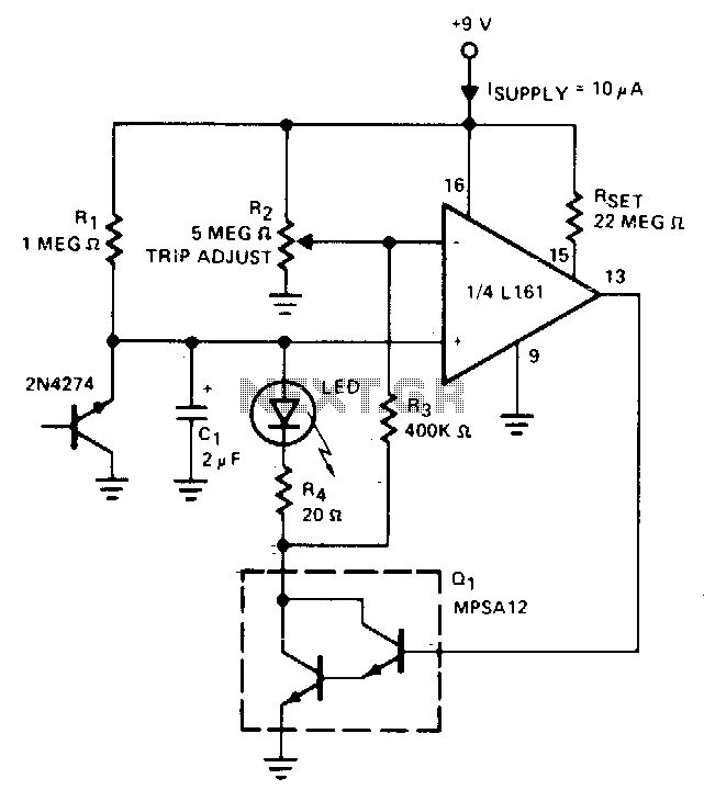
The indicator flashes an LED when the battery voltage drops below a certain threshold. The 2N4274 emitter-base junction serves as a zener diode, establishing approximately 6V on the L161's positive input. As the battery voltage decreases, the output of...
This document presents a schematic diagram of an electret microphone pre-amplifier utilizing the LMV721 operational amplifier. The LMV721 is chosen for its low noise and low power characteristics. The electret microphone pre-amplifier circuit is designed to amplify the weak audio...