
Cd4049 Amplifier
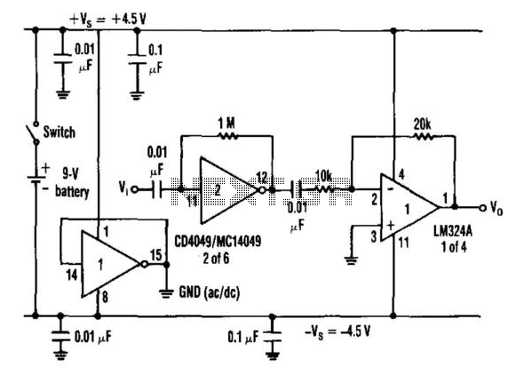
In this configuration, the inverter serves a dual purpose: it functions as an amplifier while simultaneously providing a stable dc ground reference. The resistor value, ranging from 100 kΩ to 10 kΩ, is critical in defining the gain characteristics of the inverter. The capacitor coupling ensures that only AC signals are amplified, while DC levels are maintained by the inverter's output. This setup is particularly useful in battery-powered applications where space and efficiency are paramount.
By utilizing a single battery, the inverter allows for a pseudo-dc ground, which is essential in systems that require a split power supply without the need for multiple batteries. This method reduces complexity and component count, making the design more efficient. The inverter's low impedance output ensures that the dc ground can handle varying return currents, providing stability across different load conditions.
Capacitor bypassing on the supply buses is critical to prevent noise and ensure stable operation of the inverter. This bypassing minimizes voltage fluctuations and enhances the overall performance of the circuit.
When configured as a voltage regulator, the inverter can effectively divide the battery voltage, allowing for a balanced output that can power other components, such as operational amplifiers. The LM324A, for instance, can operate effectively in this setup, benefiting from the stable dc ground provided by the inverter. This approach is advantageous as it eliminates the need for discrete resistor networks, which can introduce tolerances and inefficiencies.
Overall, this innovative use of an inverter not only simplifies the design but also enhances performance, making it suitable for a wide range of electronic applications where efficiency and reliability are critical. When an inverter is biased with one resistor from its input to output in the range of 100 KOhmhm to 10 and is capacitor c oupled, it exhibits amplifier characteristics (see the table). Furthermore, when a split power-supply bus is needed and only one battery is used, the inverter can be configured to supply a pseudo-dc ground of relatively low impedance, coincident with the ac ground (see the figure). Depending on the magnitude of the dc ground return currents, anywhere from one inverter to several in parallel are sufficient.
Also, the supply buses must be capacitor bypassed. The configured input-to-input shorted inverter now acts as a voltage regulator that sinks and sources current. In this configuration, the inverter is forced to operate at the midpoint of its transfer characteristic.
This divides the battery potential into two equal parts—as referenced to the defined dc ground by virtue of its internal gain and physical structure. Op amps such as the LM324A, can be powered from one battery while being referenced to the dc ground that is generated by the inverter.
This novel technique surpasses the use of discrete resistors for battery potential dividing. It can be employed in other applications where individual component savings and improved design performance are needed. 🔗 External reference
Related Circuits
What is so special? First of all, it has a very low harmonic distortion. Typically, manufacturers indicate the maximum power of their products with a harmonic content of 10%. In contrast, this chip achieves a harmonic distortion of only...
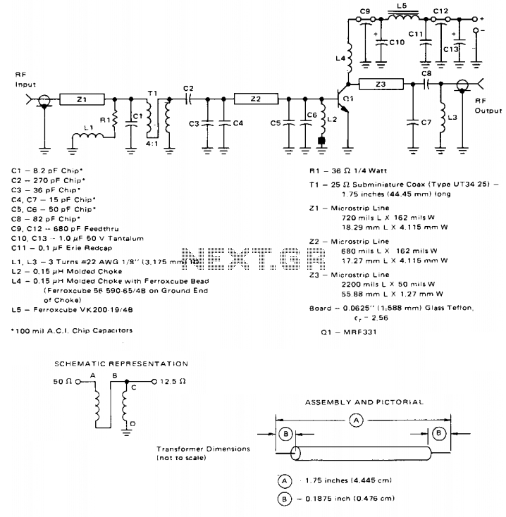
This broadband amplifier operates within the 225-400 MHz military communications band, delivering an RF output power of 10 watts while powered by a 28-volt supply. It is suitable for use as a driver for higher power devices such as...
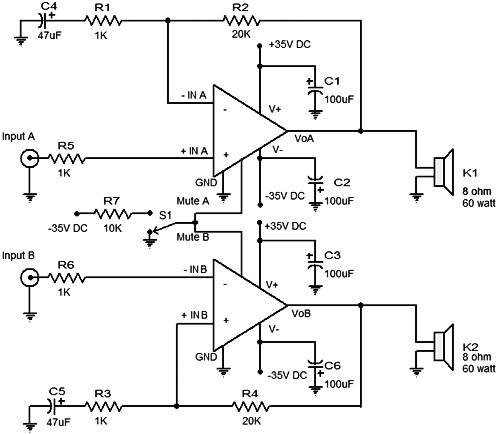
An eight watt amplifier based on the LM383 power audio amplifier IC. It's advised that you use this IC with a suitable heatsink. The LM383 power audio amplifier IC is a versatile component used in this eight-watt amplifier design....

The preamplifier circuit is designed to offer appropriate loading for phono cartridges with reluctance. It achieves a gain of approximately 25 dB at 1 kHz (converting an input of 2.2 mV to an output of 100 mV). The circuit...
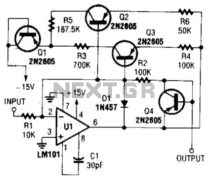
This operational amplifier circuit utilizes resistor and transistor feedback elements to function as a nonlinear amplifier. The resistors R4 and R6 can be adjusted to modify the breakpoints as needed. This operational amplifier circuit is designed to operate within the...
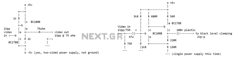
I've seen an NE592 used as a video buffer amp at the end of a 75 ohm line. Used so that the 75 ohm line could drive all kinds of neat processing stuff without affecting the signal (that's what...
Warning: include(partials/cookie-banner.php): Failed to open stream: Permission denied in /var/www/html/nextgr/view-circuit.php on line 713
Warning: include(): Failed opening 'partials/cookie-banner.php' for inclusion (include_path='.:/usr/share/php') in /var/www/html/nextgr/view-circuit.php on line 713