
Nonlinear Operational Amplifier Circuit
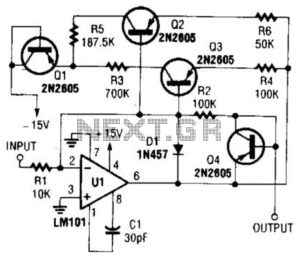
This operational amplifier circuit is designed to operate within the nonlinear region, allowing for a range of applications in signal processing where traditional linear amplification is insufficient. The inclusion of feedback elements, specifically resistors and transistors, enables the circuit to achieve desired nonlinear characteristics.
In this configuration, the operational amplifier's output is influenced by the feedback network formed by resistors R4 and R6. By varying the resistance values of R4 and R6, the circuit can be fine-tuned to achieve specific gain levels and transition points, referred to as breakpoints. These breakpoints are critical in defining the thresholds at which the amplifier transitions from one state to another, thereby influencing the overall response of the circuit to input signals.
The operational amplifier's nonlinear behavior can be particularly useful in applications such as signal clipping, waveform shaping, and dynamic range compression. The careful selection and adjustment of R4 and R6 allow for customization of the amplifier's response, making it adaptable to various signal conditions and requirements.
In practice, the circuit may also include additional components such as capacitors for stability and noise reduction, as well as diodes for protection against voltage spikes. The overall design should ensure that the operational amplifier operates within its specified limits to maintain performance and reliability. Proper layout and grounding techniques will also be essential to minimize interference and enhance the circuit's functionality. Using resistor and transistor feedback elements, this operational amplifier circuit can be used as a nonlinear amplifier. R4 and R6 can be varied to change breakpoints, as required. 🔗 External reference
Related Circuits
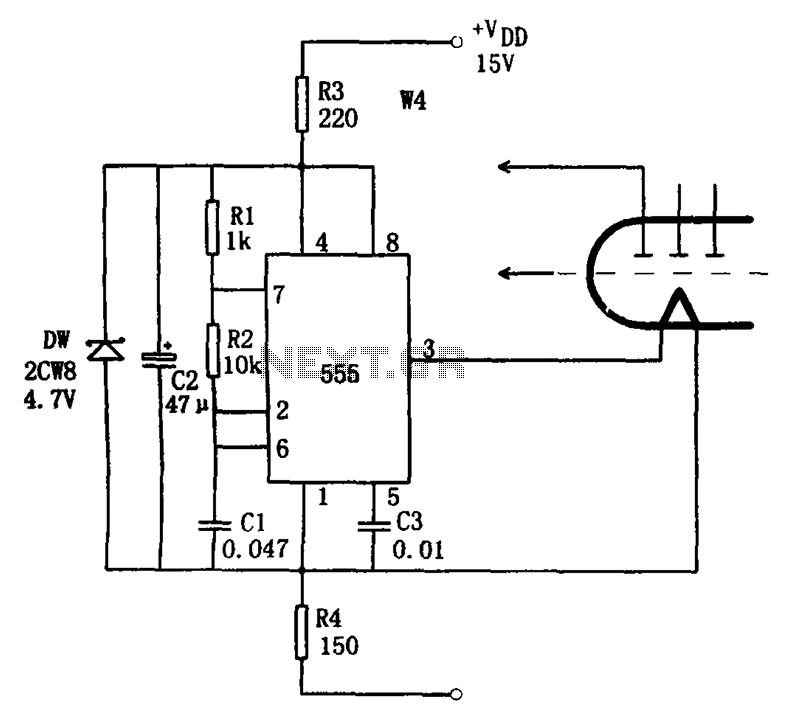
The economic fluorescent display circuit is illustrated in the figure. The primary component of this circuit is the 555 timer configured as a multivibrator. The oscillation frequency is determined by the components R1, R2, and C1, with a frequency...
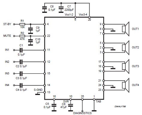
This circuit illustrates a car audio amplifier utilizing the TDA7381 integrated circuit (IC). The TDA7381 audio amplifier IC allows for the design of a straightforward 4x25 watts car radio. The TDA7381 is a high-performance audio amplifier designed specifically for automotive...
An ideal solution for making a good, low-cost power amplifier. It's an ideal solution for creating a home cinema system. The preamplifier and the driver are supported in an operational amplifier [IC1]. The voltage drop in resistors R5 and...
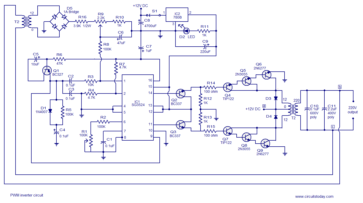
A simple PWM inverter circuit utilizes the SG3524 integrated circuit. This PWM inverter is designed for a 12V input, providing a 220V output with a maximum output power of 250 watts. The output power can be extended further. The described...
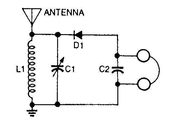
This is a very simple crystal receiver circuit for short wave band and can be used with headphones. The described circuit is a basic crystal receiver designed to operate within the shortwave frequency band. The primary components of this circuit...
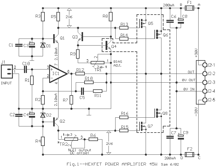
This amp uses the basic circuitry of the 60W power amp but modified for true Class-A operation. This amp has been built by several readers, and the reports I have received have been very positive. With simulations, everything appears...