
Changing the sensitivity of manual controls
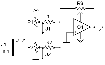
The circuit described utilizes a manual control interface (P1) to adjust various parameters of a modular synthesizer, allowing for real-time manipulation of sound characteristics. The voltage outputs generated by P1 and attenuator P2 are critical for interfacing with other components within the system. The inclusion of multiple control voltage inputs (J1) enhances the flexibility of the circuit, enabling simultaneous adjustments from various sources.
The summation point, indicated by the dashed line, plays a pivotal role in combining control voltages, ensuring that the output voltage from the operational amplifier (O1) accurately reflects the desired settings from all inputs. The sensitivity adjustments provided by resistors R1 and R2 allow for customization of the control response to suit different musical applications, making the module adaptable to varying performance needs.
In audio applications, the absence of manual control (P1) underscores the circuit's focus on handling AC signals, which require careful consideration of input levels to avoid distortion. The design of the audio input circuitry is specifically tailored to maintain signal integrity, particularly for early A-100 modules. Adjustments to the input resistors can significantly affect the performance, allowing for tailored amplification characteristics.
Overall, the modular design philosophy of the A-100 series enables users to modify and optimize their synthesizer configurations, making it a versatile platform for sound design and musical expression. The detailed resistor configuration and their impact on circuit performance highlight the importance of understanding component interactions in analog synthesizer design.P1 is the manual control of the corresponding parameter (e. g. tune for a VCO, frequency for a VCF, manual gain for a VCA, manual phase shift for a phaser and so on). P1 generates the voltage U1. J1 is the (first) input socket for the external control voltage. P2 is the corresponding attenuator. The slider of P2 outputs the voltage U2. Additional C V inputs with our without attenuators may be available (e. g. two or more CV inputs for frequency control for a VCF). The dashed line in the picture is the common point in the circuit where all CV`s are added. The output voltage of the circuit (output of O1) is used to control the corresponding parameter (tune, filter frequency, gain. ) of the module in question. The output voltage is defined by: The relations R3/R1 resp. R3/R2 determine the sensitivity of the corresponding control (P1) resp. input (J1/P2). If for example all resistors are 47k (a common value in the A-100) the sensitivity is 1 for each input.
Provided that R3 remains unchanged the resistors R1 and R2 determine the sensitivity of the corresponding control resp. input. Reducing the resistance of R1 resp. R2 increases the sensitivity of the manual control (P1) resp. input (J1/P2). Increasing the resistance of R1 resp. R2 reduces the sensitivity. To modify the sensitivity of a control knob (P1) or CV input (J1/P2) the corresponding resistor R1 resp.
R2 simply has to be changed. The audio input circuit for most A-100 modules is similar but the manual control P1 is absent (a DC offset would not make sense for an audio input, audio signals are AC signals). Normally only one audio input is available but there are exceptions (e. g. VCA A-130 and A-131, signal processor A-109). To change the sensitivity of an audio input simply the resistor R2 connected to the slider P2 of the audio input has to be replace.
A smaller value will increase the sensitivity and consequently lead to clipping/distortion for higher input levels. Especially for the first A-100 VCFs and VCAs (A-120, A-121, A-122 and first versions of A-130, A-131) the audio inputs have been designed to avoid distortion with standard A-100 signals (e.
g. VCO). Lowering the input resistors will allow distortion for these moduls too. Even the input resistors of CV or audio mixers (e. g. A-138a/b) can be changed to allow "real" amplification (i. e. > 1). The factory values of the resistors in the mixer modules A-138a/b allow a maximum amplification of about 1 (which is not really amplification). Reducing the input resistors (R2 type) or increasing the feedback resistor (R3 type) will increase the amplification of the circuit.
The factory values of the corresponding resistors (R1, R2, R3) for all modules can be found in the A-100 service manual. Normally they are in the 100k range (~ 47k. 220k). 🔗 External reference
Related Circuits
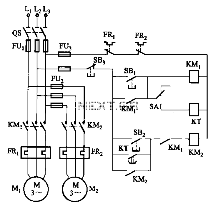
The circuit illustrated in Figure 3-85 features both manual and automatic control through the transfer switch SA. After initiating the motor Mi, an automatic start sequence is achieved via the time relay KT. The circuit employs a transfer switch (SA)...
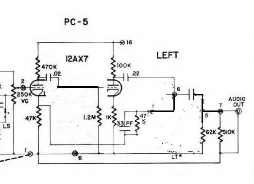
Inquiring about a simple method to bypass the tone controls in the preamplifier, with the understanding that a feedback circuit may be involved, leading to uncertainty. To bypass the tone controls in a preamplifier, one common method is to modify...
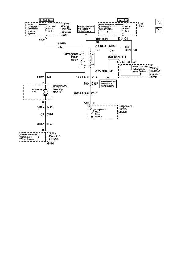
The physical location of the compressor relay is needed, as well as instructions on how to test the pressure sensor on the plastic tank of the compressor assembly. The exact location of the relay has not been confirmed, but...
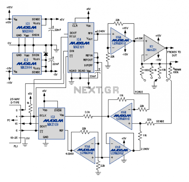
This article describes an I-V curve tracer circuit that uses a computer for display and control. The circuit is controlled via the PC parallel port. Software is provided, written in BASIC, to control the measurement and display the results...
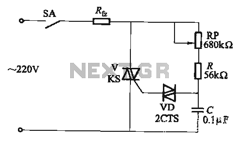
The adjustment potentiometer RP allows for the modification of the TRIAC conduction angle, facilitating temperature control applications. The adjustment potentiometer (RP) serves a crucial role in controlling the conduction angle of the TRIAC, which in turn regulates the power delivered...
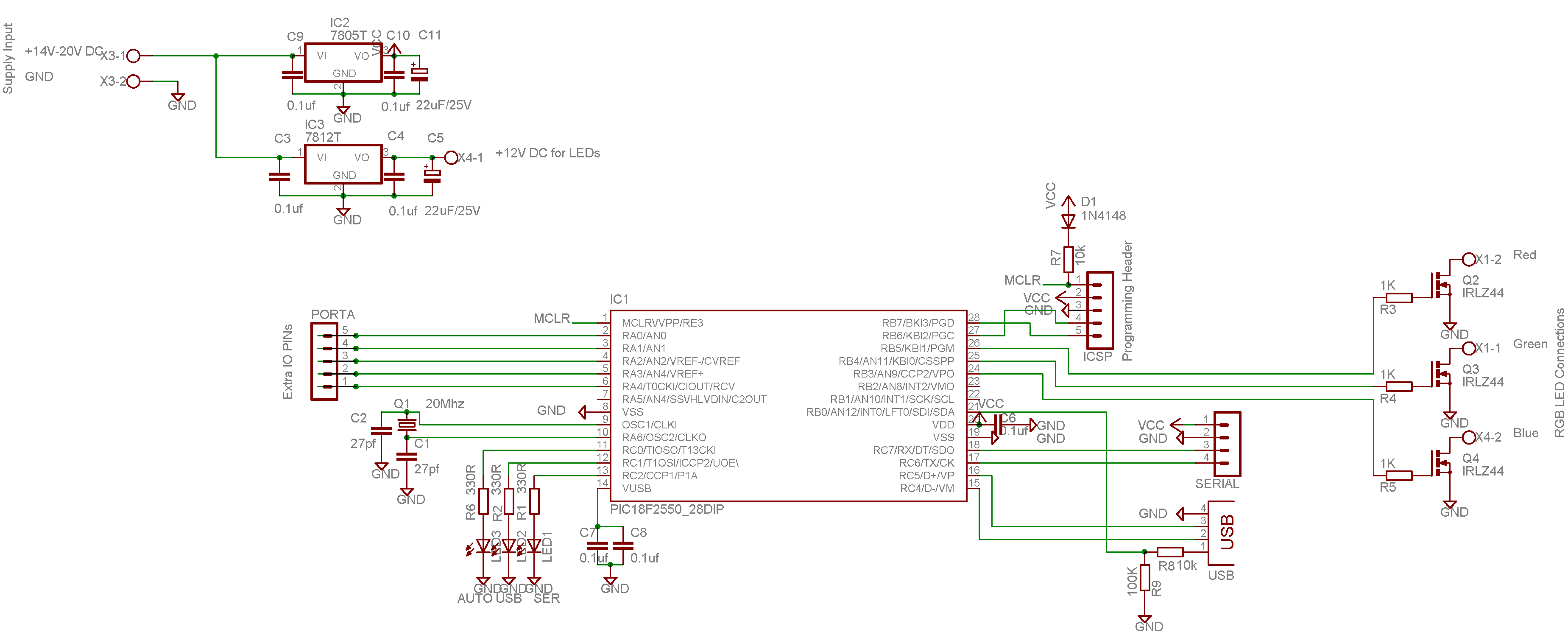
This color changer mixes light from high-power LEDs to create over 16 million colors. A smooth auto-fader cycles the colors, or it can be connected to a USB port for computer control. The device utilizes a well-known color model...