
Make a USB color changing light

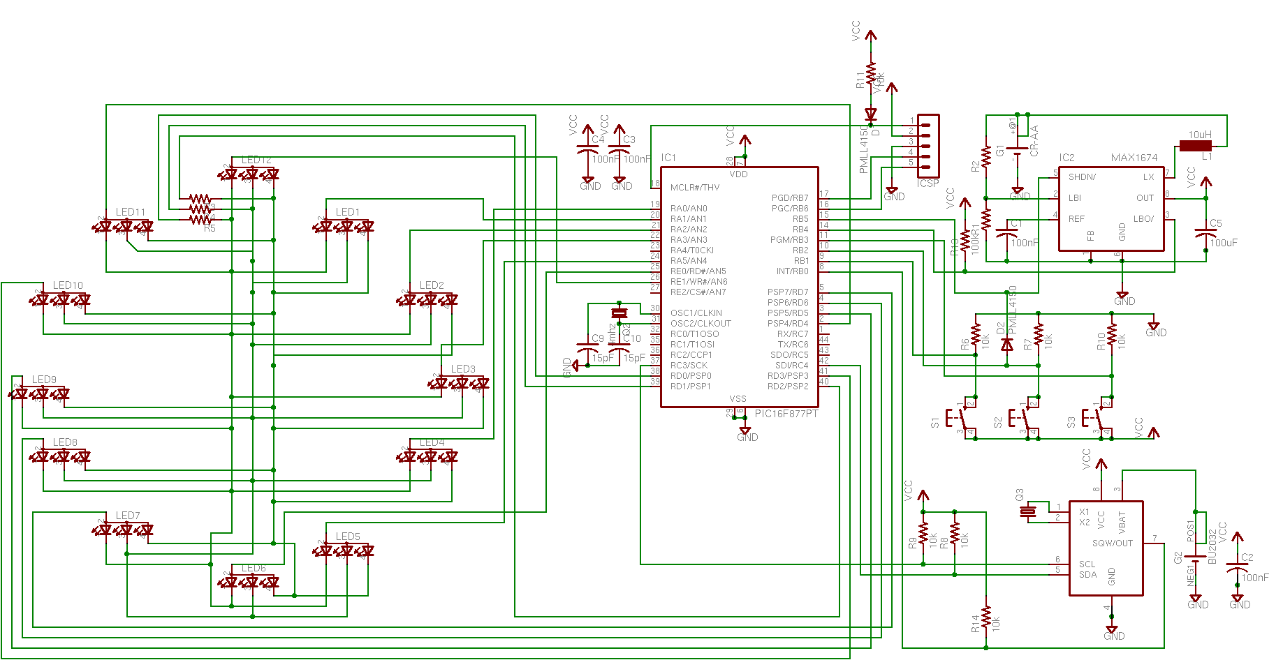
The Microchip PIC 18F2550 microcontroller (IC1) is selected for this project due to its full-speed USB connection and a firmware framework that facilitates a generic serial port to USB emulator. It provides ample program space for advanced fading programs. Supporting components include a 0.1 µF capacitor between the power and ground pins (C6), along with a resistor and diode for the ICSP programming header (R7, D1). The on-chip USB peripheral necessitates two additional 0.1 µF capacitors (C7, C8) and a 20 MHz crystal (Q1), accompanied by two 27 pF capacitors for the crystal (C1, C2). The device is designed to run a color fading program independently when not connected to USB power, functioning as a self-powered device with an external power source.
To monitor the USB power line, one microcontroller pin is utilized. When a USB cable is connected, the PIC detects the voltage and activates the USB connection. The USB power line is interfaced with the PIC through two small resistors (R8, R9) to minimize noise and protect the microcontroller. Resistor values of 100K ohm and 10K ohm are recommended, although other close values may suffice. The PIC features two hardware PWM outputs suitable for fading LEDs, but three channels are required for red, green, and blue control. Instead of using a dedicated hardware PWM device, software PWM is employed to leverage the processing power of the PIC without incurring additional costs.
Since a microcontroller pin cannot directly power multiple LEDs, the PIC controls the LEDs through transistors or MOSFETs (Q2, Q3, Q4). The design incorporates a basic LED circuit along with switching circuits utilizing FETs and transistors. An IRLZ44 MOSFET is chosen for its suitability, although various options exist. It is imperative to select a FET that can fully switch at 5 volts or lower, as indicated in the datasheet, which typically includes a graph depicting operation over a range of gate-source voltages (Vgs). A FET with a minimum gate voltage requirement of 12 volts will not operate effectively when controlled by the PIC at 5 volts.This color changer mixes light from high-power LEDs to create more than 16 million colors. A smooth auto-fader cycles the colors, or you can hook it up to a USB port and control it from your computer. This color changer borrows a well-known color model used in TVs and LCD panels. These displays blend red, green, and blue light to create a vast num ber of colors. Look closely at your monitor - this image of the DIY Life site is made of tiny red, green, and blue dots. We`ll mimic this technique by mixing light from red, green, and blue LEDs. The easiest way to dim LEDs is to blink them and vary the ratio of on and off time. If the LED blinks fast enough, we perceive it as a solid light of lower intensity. This method of dimming is known as pulse-width modulation (PWM). The figure below shows a single period in a pulse-width modulation cycle. At the start of the period, the signal is high (the LED is on) for the time defined as the duty cycle.
When the duty cycle is finished, the signal goes low (the LED is off) for the remainder of the period. Adjusting the duty cycle varies the brightness of the LED. By extending this to red, green, and blue channels, we can mix a nearly infinite number of colors. I chose the Microchip PIC 18F2550 as the microcontroller for this project (IC1). It has a full-speed USB connection and a free firmware framework for a generic serial port to USB emulator.
It`s got a ton of program space for fancy, stand-alone fading programs. As far as support gear goes, we need a 0. 1uF capacitor between the power and ground pins (C6), and a resistor and diode are needed for the ICSP programming header (R7, D1). The on-chip USB peripheral requires an additional two 0. 1uF capacitors (C7, 8) and a 20 MHz crystal (Q1)- don`t forget two 27pF caps for the crystal (C1, 2).
Crystals vary, but 27pF capacitors usually work. The device should continue to run a nice color fading program when the USB isn`t connected. This type of USB device is `self powered` - it has an external power source and runs independently of the USB connection. This setup requires one microcontroller pin to monitor the power line of the USB cable. When a cable is attached, the PIC senses a voltage and opens the USB connection. The USB power line is connected to the PIC through two small resistors (R8, 9), in order to cut down on noise and protect the chip.
I used 100K ohm and 10K ohm resistors, but any close values should work fine. The PIC has two hardware PWMs that could be used to fade LEDs, but we need a total of three channels - one each for red, green, and blue. We could use a hardware device, but with so much power in the PIC we can do it in software without the added expense.
A microcontroller pin is unable to power more than a few LEDs directly. Instead, the PIC will switch the LEDs with a transistor or MOSFET (Q2, 3, 4). This diagram shows a simple LED circuit, and switching circuits that use a FET and transistor. I used an IRLZ44 MOSFET, but there are many options. You should choose a FET that switches completely at 5 volts or less. The data sheet usually has a graph of operation over a range of switching voltages (Vgs). A FET with a minimum gate voltage of 12 volts will never turn on when switched by the PIC running at 5 volts. 🔗 External reference
Related Circuits
Christmas is approaching, and it is the time of year when electronics students and hobbyists consider creating a Christmas circuit for their homes, particularly one that features flashing lights. Numerous circuits and kits are available that can flash various...
With the phasing out of game, serial, and parallel ports from modern computers and the increasing popularity of USB, it is beneficial for hobbyists to learn how to work with USB. However, USB is a complex protocol that can...
Moderately priced Passive Infrared (PIR) sensor modules are now widely available. By using these readymade and pre-configured PIR sensors, even an average electronics enthusiast can implement motion detection systems effectively. Passive Infrared (PIR) sensors are devices that detect infrared radiation...

The Car LED Light Sequencer utilizes a standard 74C164 8-bit shift register as its main component. The 74C164, also referred to as an 8-Bit Parallel-Out Serial Shift Register, is a monolithic complementary MOS (CMOS) integrated circuit. This 8-bit shift...

This circuit generates a pulse when an object on the conveyor belt obstructs the light source. The light source continuously keeps the phototransistor activated, resulting in a high logic level voltage at the Schmitt-trigger inverter and a TTL-compatible low...
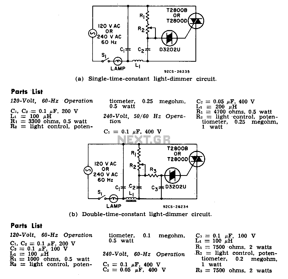
The two lamp-dimmer circuits differ in that one employs a single-time-constant trigger network, while the other uses a double-time-constant trigger circuit. This second configuration reduces hysteresis effects and extends the effective range of the light-control potentiometer. Hysteresis refers to...