
charger for car battery
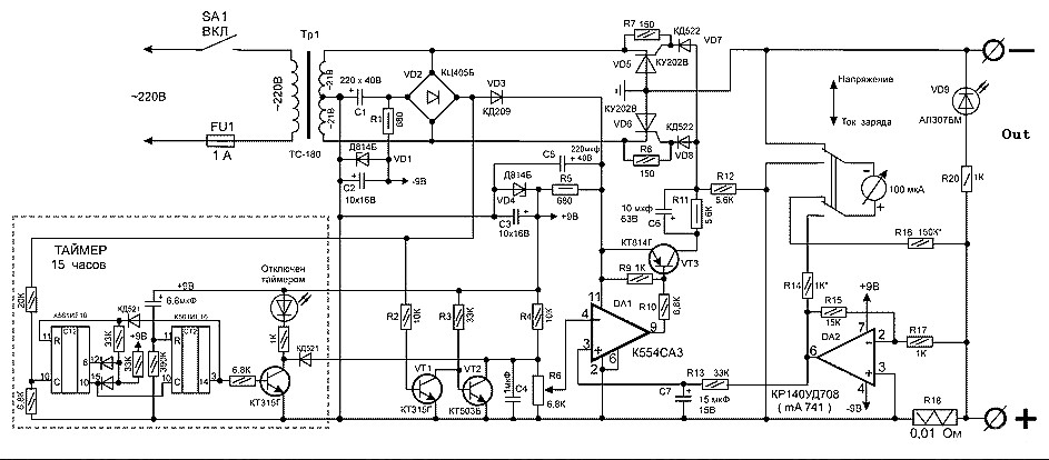
The battery charger circuit utilizes the LM393 voltage comparator IC to monitor the charging process of a 12V lead-acid battery. The essential function of this circuit is to provide a visual indication of the charging status, ensuring that users can easily determine whether the battery is receiving charge.
The circuit operates by comparing the voltage level at the battery terminals with a predefined reference voltage. When the battery is connected to the charger, and the charging current exceeds 25 milliamps, the LM393 activates the LED indicator (D1). This LED serves as a simple yet effective way to convey the charging status to the user.
The design incorporates necessary components such as resistors and capacitors to stabilize the operation of the LM393 and ensure accurate voltage comparisons. The use of a voltage comparator allows for precise monitoring of the battery's state, which is crucial for maintaining battery health and preventing overcharging.
Additionally, the circuit can be customized with different reference voltages to accommodate various battery types and capacities. This flexibility makes it a versatile solution for a range of battery charging applications. Overall, this battery charger indicator circuit is an efficient means to enhance battery management systems, providing users with real-time feedback on charging activity.Charger for Car Battery power supply. Go to that page to read the explanation about above power supply related circuit diagram. Description ofbatterycharger indicator: The circuit above willmakeyoursimplebatterychargerlook sophisticated. This circuit is a charging indicator forbatterycharger. Its usedtoche ckwhether thebatteryis chargingornot. VoltagecomparatorLM393 ICis the heartofthis Battery charger indicator circuit. D1LEDstays litwhenthere areat least 25milli-amps of currentwhich flowsto the battery. This circuit isdesignedspecifically for12Vbatterywith. 🔗 External reference
Related Circuits
This simple circuit drives six LEDs in a "Knightrider scanner mode." Power consumption primarily depends on the type of LEDs used, especially if a 7555 (555 CMOS version) is utilized. The circuit operates by sequentially illuminating the LEDs to create...
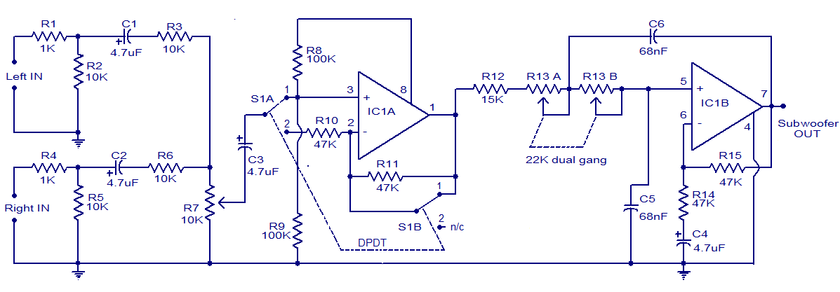
The circuit diagram depicts a simple subwoofer filter that operates on a 12V DC supply, making it particularly useful for automobile subwoofer applications. This circuit functions as a low-pass filter, with an adjustable pass frequency ranging from 60 to...
The circuit indicates two different water temperature trip points by activating LEDs when the specified temperatures are reached. It is built around the LM2904 dual operational amplifier, which is powered by a 12 V automotive system. A thermistor is...
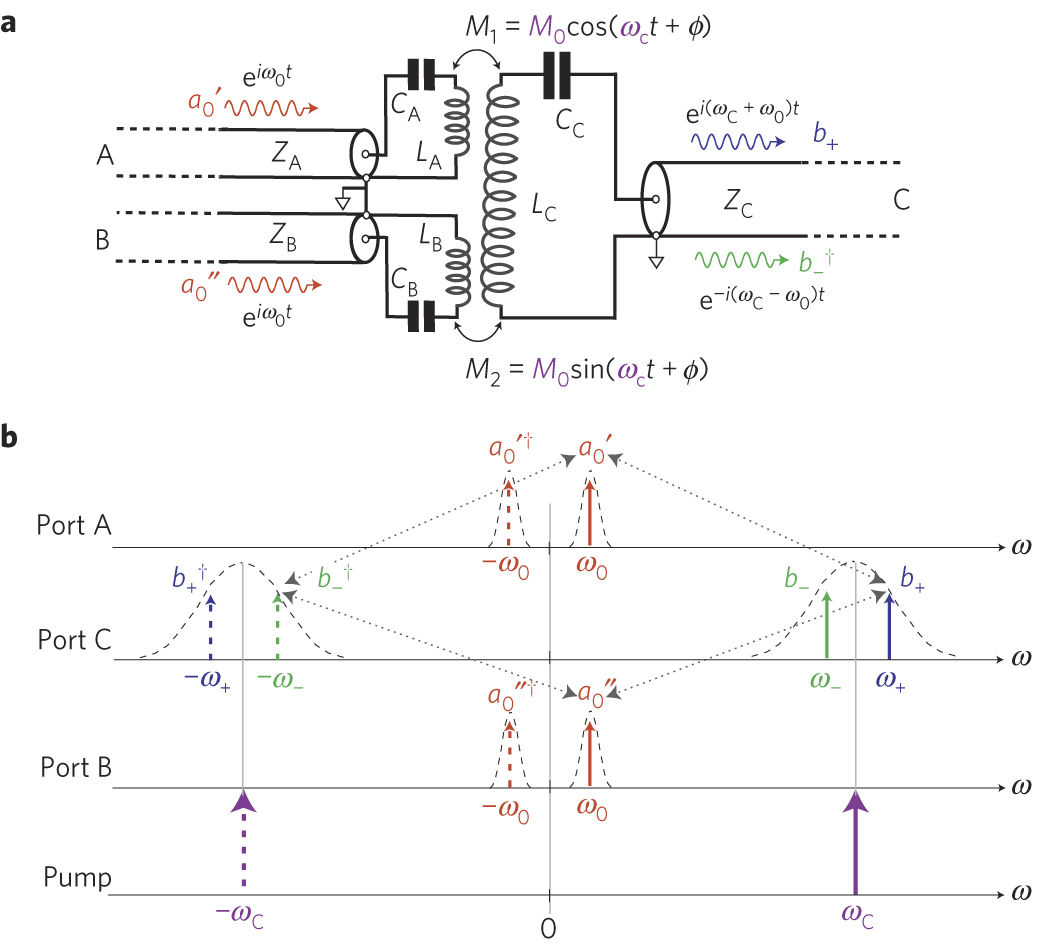
The circuit schematic of the UDC consists solely of dispersive components. Two low-frequency series LC resonators, with equal inductances (LA=LB) and capacitances (CA=CB), are connected to two input semi-infinite transmission lines, designated as A and B. These resonators are...
A battery-powered, pushbutton-triggered TTL/CMOS-compatible source of debounced 5V logic pulses is a simple but handy piece of test equipment to have in any tool kit. The circuit's battery-powered operation complicates what would otherwise be a trivial exercise in switch-bounce...
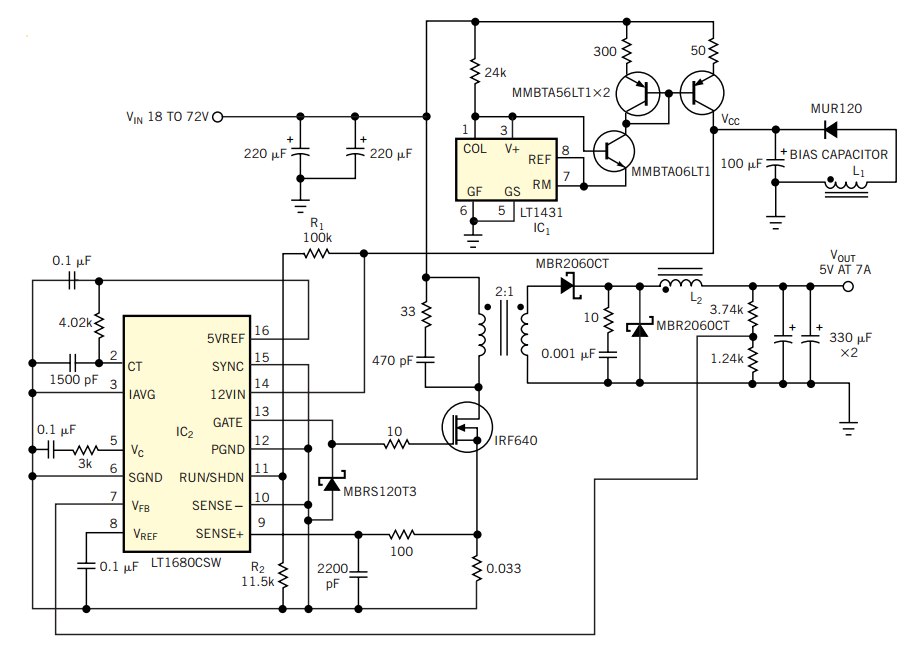
Switch mode circuits can implement a lead acid battery charger more efficiently. It can be constructed using the bq24105 battery charger controller. Switch mode power supplies (SMPS) are widely recognized for their efficiency and compactness, making them suitable for applications...
Warning: include(partials/cookie-banner.php): Failed to open stream: Permission denied in /var/www/html/nextgr/view-circuit.php on line 713
Warning: include(): Failed opening 'partials/cookie-banner.php' for inclusion (include_path='.:/usr/share/php') in /var/www/html/nextgr/view-circuit.php on line 713