
tl072 car subwoofer filter circuit
The subwoofer filter circuit is designed to enhance the bass response in audio systems, particularly in automotive environments where space and power constraints are prevalent. The TL072 opamp is chosen for its low noise and high-speed performance, which is essential for maintaining audio fidelity. The buffer configuration of IC1A ensures that the audio signal retains its integrity while allowing for impedance matching between the audio source and the filter circuit.
The DPDT switch S1 plays a critical role in the circuit by allowing the user to select between different configurations, enabling flexibility in the audio output. Positioning the switch to induce a 180-degree phase shift can help in optimizing the subwoofer performance, especially in setups where multiple speakers are used, ensuring that sound waves are properly aligned for a coherent audio experience.
Potentiometer R7 serves as a volume control, enabling the user to adjust the output level of the subwoofer, thus providing a tailored listening experience. The low-pass filter implemented by IC1B is crucial for eliminating high-frequency noise and allowing only the desired bass frequencies to pass through. The adjustable cutoff frequency, controlled by the dual gang potentiometer R13, provides the ability to fine-tune the filter's response, accommodating various audio preferences and speaker characteristics.
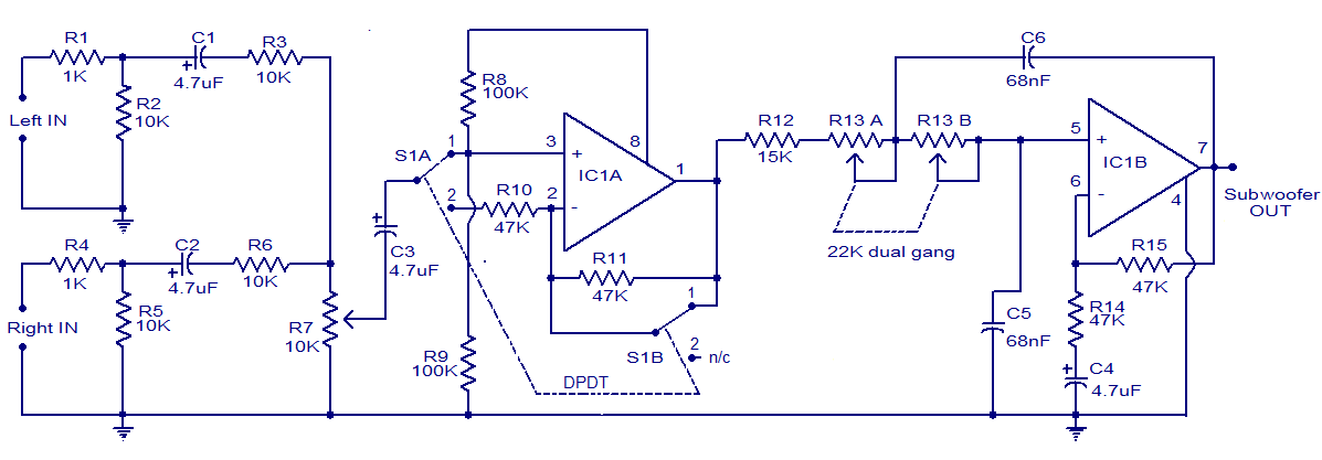
Overall, this subwoofer filter circuit is a versatile solution for enhancing low-frequency audio performance in automotive applications, combining simplicity and effectiveness in design.Here is the circuit diagram of an easy subwoofer filter that can be operated from a 12V DC supply. Such a circuit is incredibly helpful in automobile subwoofer applications. The circuit is nothing however a low pass filter whose pass frequency can be adjusted between 60 to 160 Hz. The circuit is designed based on the TL072 dual BIFET opamp IC. Out of the two opamps inside the chip, IC1A is wired as a buffer. The left and right audio inputs when mixing is fed to the input of the IC1A using the DPDT switch S1. Switch S1 is the part control switch which can be used to create the subwoofer in part with different speakers.
When S1 is in position 2, 180 degree part shift will be induced. POT R7 can be used for controlling the level. IC1B forms the low pass filter whose pass frequency can be controlled by adjusting the dual gang POT R13. 🔗 External reference
Related Circuits
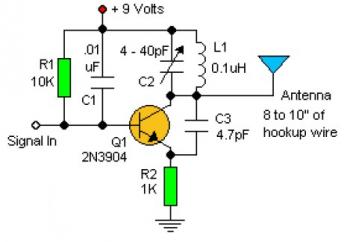
Experimenting with the size of the coil and the number of turns can influence the frequency and signal output of the oscillator. The signal can be received using a standard FM radio receiver. The input signal should be coupled...
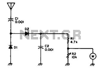
Useful for checking transmitters and antennas, this circuit utilizes a voltage-doubling detector consisting of diodes D1 and D2, which can be HP 5082-2800 hot carrier types or alternatives such as 1N34 or IN82. The circuit incorporates a 100-mA meter...
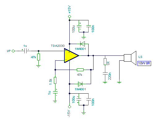
Connecting two TDA2030 through inexpensive power transistors allows for the creation of an amplifier capable of delivering higher power. This can be achieved by utilizing the component values specified in the schematic. To implement this circuit, two TDA2030 integrated circuits...
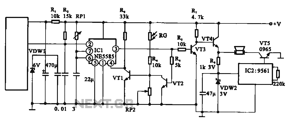
This circuit illustrates an automatic unattended burglar alarm system designed primarily for residential use, warehouses, and similar applications. The circuit features a pyroelectric infrared sensor integrated with a light control mechanism. It comprises components such as resistors (RG, RP2,...
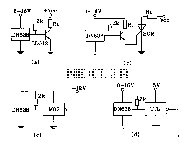
Figures (A), (B), (C), and (D) illustrate outputs that can directly drive transistors, thyristors, relays, CMOS circuits, and TTL circuits. The described figures depict various output configurations capable of interfacing with different electronic components. Each output is designed to provide...

The R-C twin-tee passive circuit provides band-reject (notch) filtering suitable for portable applications. It has a loaded circuit Q of 0.25. Effective rejection is achievable when the bridge is balanced, which requires close tolerances of the adjustable components, and...