
circuit 9 second countdown power on
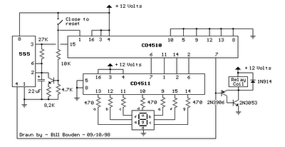
The described circuit comprises a 555 timer configured in astable mode to generate a clock signal with a frequency of approximately 1 Hz. This clock signal is utilized to decrement a binary counter, typically a 74HC4040 or similar, which counts down from a preset value (in this case, 9). The counter output is monitored, specifically the carry-out signal at pin 7, which indicates when the counter has reached zero.
When the switch is opened, the timer begins its operation, producing a pulse every second. Each pulse causes the counter to decrement its value until it reaches zero. At this point, the carry-out signal transitions to a low state, which activates a relay. The relay operates at 12 volts and is often used to control higher power loads, providing isolation between the low voltage control circuit and the high voltage output.
The output from the relay can be used to control various devices or indicators. The circuit is designed to stop the timer when the carry-out signal goes low, achieved through a low signal applied to the reset pin (pin 4) of the timer. This effectively halts the clock signal generation, preventing further counting.
The relay remains energized until the switch is closed again, which serves as a manual reset mechanism for the counter. Closing the switch sends a high signal to the reset input of the counter, returning it to its initial state (count of 9). Additionally, the duration of the clock signal can be fine-tuned by adjusting the resistor connected to pin 3 of the 555 timer. This allows for flexibility in timing applications, accommodating different requirements for the timing interval.
This circuit can be employed in various applications, including timers for automatic systems, delay circuits, or any scenario where a timed output is required. Proper selection of components and values will ensure reliable operation and desired performance characteristics.When the switch is opened, the timer produces an approximate 1 second clock signal, decrementing the counter until the 0 count is reached. When the zero count is reached, the `carry out` signal at pin 7 of the counter moves low, energizing the 12 volt relay and stopping the clock with a low signal on the reset line (pin 4).
The relay will remain e nergized until the switch is again closed, resetting the counter to 9. The 1 second clock signal from the 555 timer can be adjusted slightly longer or shorter by increasing or decreasing the resistor value at pin 3 of the timer. 🔗 External reference
Related Circuits
For bikers or scooter riders, it is common to forget to cancel flashing indicators after making a turn, especially without an audible reminder. Continuously checking indicator lamps is impractical, as attention should remain focused on the road. The circuit...
The PLL synthesizer oscillator circuit is a feedback loop consisting of a reference oscillator, phase comparator, loop filter, voltage-controlled oscillator, programmable frequency divider, and various other components. In this circuit, the reference oscillator employs a crystal oscillator (OSC) to...
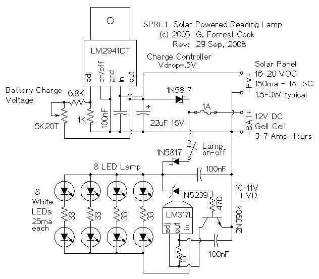
The reading lamp consists of a small solar panel, a standard UPS style lead acid battery, and an LED circuit board. The circuit board contains a low power solar charge controller (regulator), a set of 8 white LEDs, a...
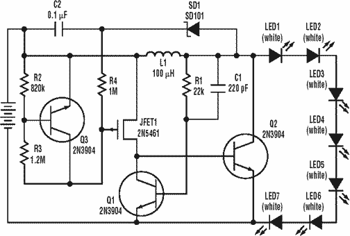
A low power, long-life LED flashlight circuit. Electronic Design proposed a simple circuit to resolve this in a recent article. The front end of their circuit draws less than a milliamp of extra current. The described LED flashlight circuit is...
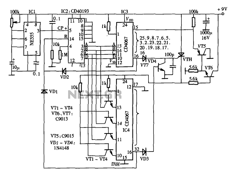
The lantern control circuit allows for the management of 30 outputs through an external driver circuit, specifically designed for water sports or large decorative lantern applications. The circuit features a control pulse generator, which regulates the lights, and an...
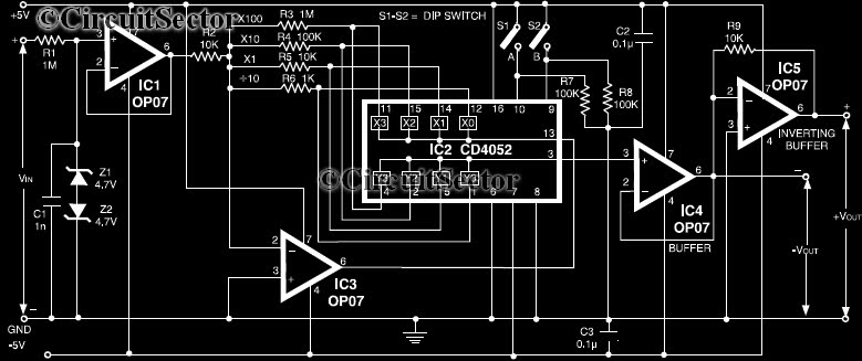
This circuit is a precision amplifier with digital control, designed for signal conditioning of low-output transducers operating in the millivolt range. The resistors R3 to R6 can be user-selected, with values ranging from 1 kilo-ohm to 1 mega-ohm, allowing...