
Digital Controlled Precision Amplifier Circuit PCB
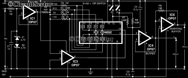
This precision amplifier circuit is particularly advantageous for applications requiring accurate signal amplification from low-output transducers, such as thermocouples or strain gauges. The selection of resistors R3 to R6 allows for fine-tuning of the gain, which is critical for optimizing the performance based on the specific characteristics of the transducer being used. The range of resistor values ensures versatility in gain settings, accommodating various signal levels encountered in practical scenarios.
Capacitor C1 plays a crucial role in maintaining signal integrity by filtering out high-frequency noise and ripples that could distort the measurement. The inclusion of Z1 and Z2 as voltage limiters protects the circuit from over-voltage conditions, thereby enhancing its reliability and longevity. This feature is particularly important in environments where transducer outputs may fluctuate unexpectedly.
The use of op-amp IC1 not only boosts the input impedance but also minimizes the risk of measurement errors due to floating inputs. This is essential in precision applications where even the slightest variations can lead to significant inaccuracies. The inverting buffer amplifier configuration provided by IC5 ensures that the signal maintains its integrity and polarity throughout the amplification process. Meanwhile, IC4's role as an output buffer isolates the amplifier's output from the load, ensuring stable operation regardless of the subsequent circuitry.
Furthermore, the integration of CD4051/52 multiplexers allows for sophisticated control over the gain settings, enabling users to select from eight different gain or attenuation levels. This digital control capability enhances the usability of the circuit in automated measurement systems, where precise adjustments may be necessary based on varying conditions or requirements.
Overall, this precision amplifier circuit is a robust solution for low-level signal amplification, combining flexibility in gain selection with essential protective features and high input impedance for accurate measurements.Here is a circuit of a precision amplifier with digital control can be useful for signal conditioning of low output transducers in milli volt range. The resistors R3 to R6 can be selected by the user and can be anywhere from 1 kilo-ohm to 1 meg-ohm to select the appropriate gain of the precision amplifier.
C1 reduce ripples in the voltage and Z1 an d Z2 limits input voltage to +- 4. 7V Precision amplifier circuit shown in figure, The IC1 opamp us used to increase the input impedance to avoid floating of the inputs when no measurement is being made. IC5 is used to restore the polarity of the input and works as an inverting buffer amplifier while IC4 is an output buffer.
Eight steps for gain or attenuation can be added by using two CD4051/52 🔗 External reference
Related Circuits
The amplifier drives a pair of loudspeakers using two LM3876 integrated power amp ICs (50 watts per channel), or a pair of headphones via a Meier crossfeed filter and an OPA2134 dual opamp. It provides four switchable line level...
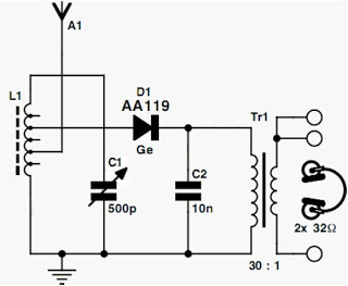
Currently, the most commonly available headphones have an impedance ranging from 2 to 32 ohms. This relatively low value renders them unsuitable for certain designs. However, with some clever modifications, these headphones can be effectively utilized in such applications....
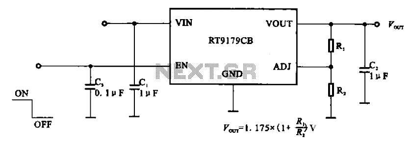
The RT9179CB is a power management chip utilized in power supply circuits. It serves as a linear regulator power management chip. This circuit is commonly employed in various products, such as computer motherboards, LCD monitors, and others. It is...
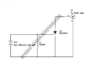
The following circuit illustrates a Slave Flash Light Control Circuit Diagram. Features include a 68mH inductor that provides an automatic trigger for the secondary flash light. The Slave Flash Light Control Circuit is designed to manage the operation of a...
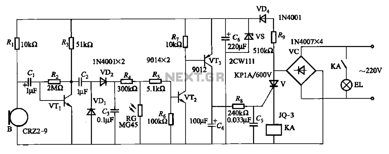
A resistor R8, capacitors Cd, and a thyristor V AC switch form a delay circuit. The lamp's lighting delay time is determined by the resistor Rs and capacitor C4, with a delay of approximately 40 seconds as indicated in...
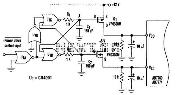
This circuit adds a power-down function to analog I/O ports, such as the AD7769 and AD7774. Additionally, the diodes typically required to protect the devices against power-supply mis-sequencing can be eliminated. In this design, MOSFETs Q1 and Q2 switch...