
Circuit Diagram Of 60 Hz Frequency Signal Generator

This circuit is designed to generate a stable 60 Hz sine wave output, which is commonly used in various applications such as clock signals, audio signal generation, and power supply synchronization. The primary component responsible for frequency generation is the feedback loop, which includes the 0.068 µF capacitor. This capacitor, along with resistors and possibly an inductor, forms an RC or RLC circuit that determines the oscillation frequency.
In a typical implementation, an operational amplifier (op-amp) may be utilized to amplify the output signal while maintaining stability. The feedback loop ensures that a portion of the output is fed back to the input, creating a condition for sustained oscillations. The values of the resistors and capacitors in the feedback loop are critical, as they set the time constant of the circuit, thereby influencing the frequency of oscillation.
To achieve a clean sine wave output, additional filtering may be employed. This could involve using low-pass filters to eliminate higher harmonics generated during the oscillation process. Furthermore, the circuit may include a power supply section to convert DC voltage into the necessary AC signal, ensuring that the output meets the required specifications for the intended application.
Overall, the design of a stable 60 Hz frequency signal generator circuit is a fundamental aspect of electronic engineering, providing a reliable source of oscillation for various electronic devices and systems.The following circuit Shows about Stable 60 Hz Frequency Signal Generator Circuit Diagram. Features:0.068uF caps inside a feedback loop, DC-to-AC .. 🔗 External reference
Related Circuits
This circuit employs an HgCdTe demodulation device that can be cooled to 77K using liquid nitrogen. It utilizes a constant current bias for the demodulation device, which is connected to the input port. The voltage amplification factor is 200,...
This circuit is designed for alerting purposes after a predetermined time has elapsed. It is ideal for tabletop games that require a fixed duration for answering questions or moving pieces. In this context, it serves as a modern alternative...
This schematic has been modified from an old Bell & Howell projector amplifier for model 302, utilizing PP 6V6 tubes with a 12AU7 phase inverter (PI). The PI circuit appears to be closest to a "floating paraphase." There is...
NOTE: There is no guarantee as to the suitability of said circuits and information for any purpose whatsoever other than as a self-training aid. I.E. If it blows your equipments, trashes your hard disc, wipes your backup, burns your...
Four simple 12V power supply circuits are designed to provide output voltages close to 12V. The first power supply circuit utilizes a BD139 transistor, a zener diode, and several passive components. Each schematic is straightforward to assemble and will...
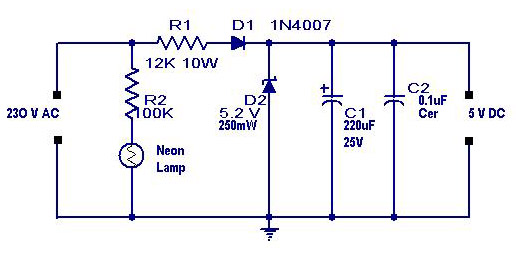
A simple transformerless power supply circuit with a diagram and schematics that provides a 5 volts DC output. This is a low-cost, low-current power supply circuit suitable for simple applications such as powering an LED. The transformerless power supply circuit...