
Circuit Diagram Of Motor Control Unit Based On The LM317 IC
The motor control unit circuit utilizes the LM317 voltage regulator to provide a stable output voltage, which is essential for controlling the speed of a DC motor. The LM317 is a versatile adjustable voltage regulator that can output voltages from 1.25V to 37V, making it suitable for various motor applications.
In this circuit, the LM317 is configured with two resistors to set the output voltage according to the desired motor speed. The output voltage can be adjusted by changing the resistance values, allowing for precise control over the motor's operation. The circuit also incorporates diodes to safeguard the LM317 from potential back EMF generated by the motor during operation. This protection is crucial as it prevents damage to the regulator and ensures longevity and reliability of the circuit.
Additionally, capacitors may be included in the circuit design to stabilize the voltage and reduce noise, enhancing the overall performance of the motor control unit. The inclusion of heat sinks for the LM317 is also recommended, as the regulator may dissipate significant heat during operation, especially under high load conditions.
Overall, this motor control unit circuit provides an effective solution for controlling DC motors, combining the adjustable output capability of the LM317 with protective measures to ensure robust performance in various applications.The following circuit show about Circuit Diagram Of Motor Control Unit. This circuit based on the LM317 IC. Features:diodes protect the regulator, . 🔗 External reference
Related Circuits
In a hybrid system, an analog system with digital control, voltage-controlled components are crucial as they can be interfaced with a Digital-to-Analog Converter (DAC) from the digital system. In hybrid systems, the integration of analog and digital components allows...
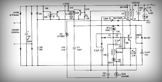
This is a low voltage, high-current output switching DC power supply with an input of 220 volts AC. In this circuit, an ST2 DIAC relaxation oscillator, Q3, C1, and the DIAC initiate conduction of the output switching transistor Q1....
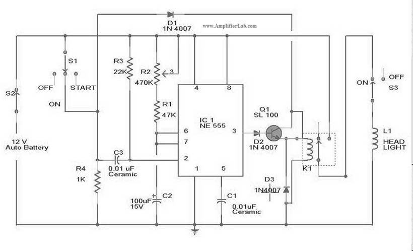
The circuit diagram for the automatic headlights turn-off circuit is presented here. This circuit can be installed in a car. The automatic headlights turn-off circuit is designed to enhance vehicle safety and convenience by ensuring that the headlights are automatically...
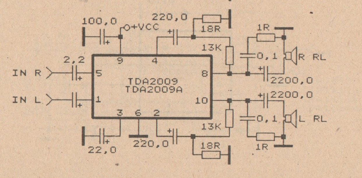
The minimum voltage required for this circuit is 8 volts, while the maximum voltage is 28 volts. It can be used to amplify audio signals in electronic devices such as radios, DVDs, MP4 players, and MP5 players. The circuit...
These devices are low-cost, high-speed, dual JFET input operational amplifiers featuring an internally trimmed input offset voltage (utilizing BI-FET II technology). They require low supply current while maintaining a large gain-bandwidth product and fast slew rate. Additionally, well-matched high-voltage...
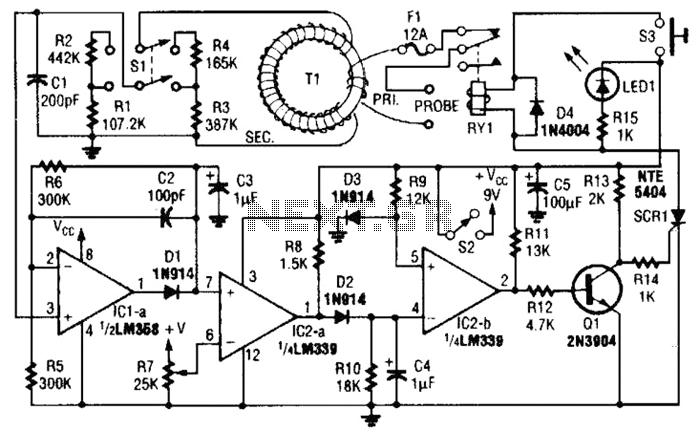
This circuit is an adjustable electronic circuit breaker that features a toroidal transformer designed to sense a 60-Hz load current. The transformer, labeled as T1, has a two-turn winding for the primary side and 100 turns of #30 gauge...