
Automatic Car Head Lights Turn-off Circuit
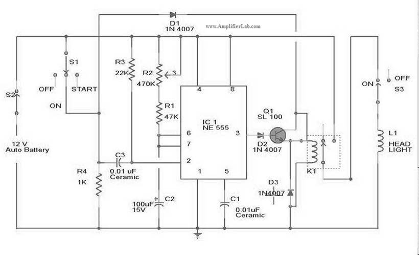
The automatic headlights turn-off circuit is designed to enhance vehicle safety and convenience by ensuring that the headlights are automatically turned off after a predetermined time when the vehicle is parked. This circuit typically utilizes a timer integrated circuit, such as the NE555, which is configured in monostable mode to achieve the desired time delay.
In this circuit, the headlights are connected through a relay, which is controlled by the output of the timer. When the vehicle's ignition is turned off, the timer is activated, initiating the timing sequence. The duration for which the headlights remain on can be adjusted by changing the resistor and capacitor values connected to the timer IC.
The circuit also includes a switch that can be manually overridden to turn off the headlights immediately, regardless of the timer. Additionally, a diode is included to prevent back EMF from the relay coil, protecting the timer IC from potential damage.
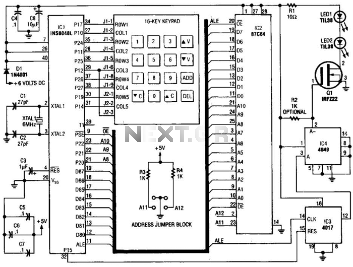
For installation, the circuit requires a power source that is only active when the ignition is off, typically sourced from the vehicle's battery. Proper connections to the vehicle's lighting system and the relay are crucial for reliable operation. This automatic headlight turn-off circuit not only prevents battery drainage but also ensures that the vehicle's lights are managed efficiently, contributing to overall vehicle functionality and user experience.The circuit diagram of Automatic head lights turn off circuit has been explained here. This circuit can be installed in a car. 🔗 External reference
Related Circuits
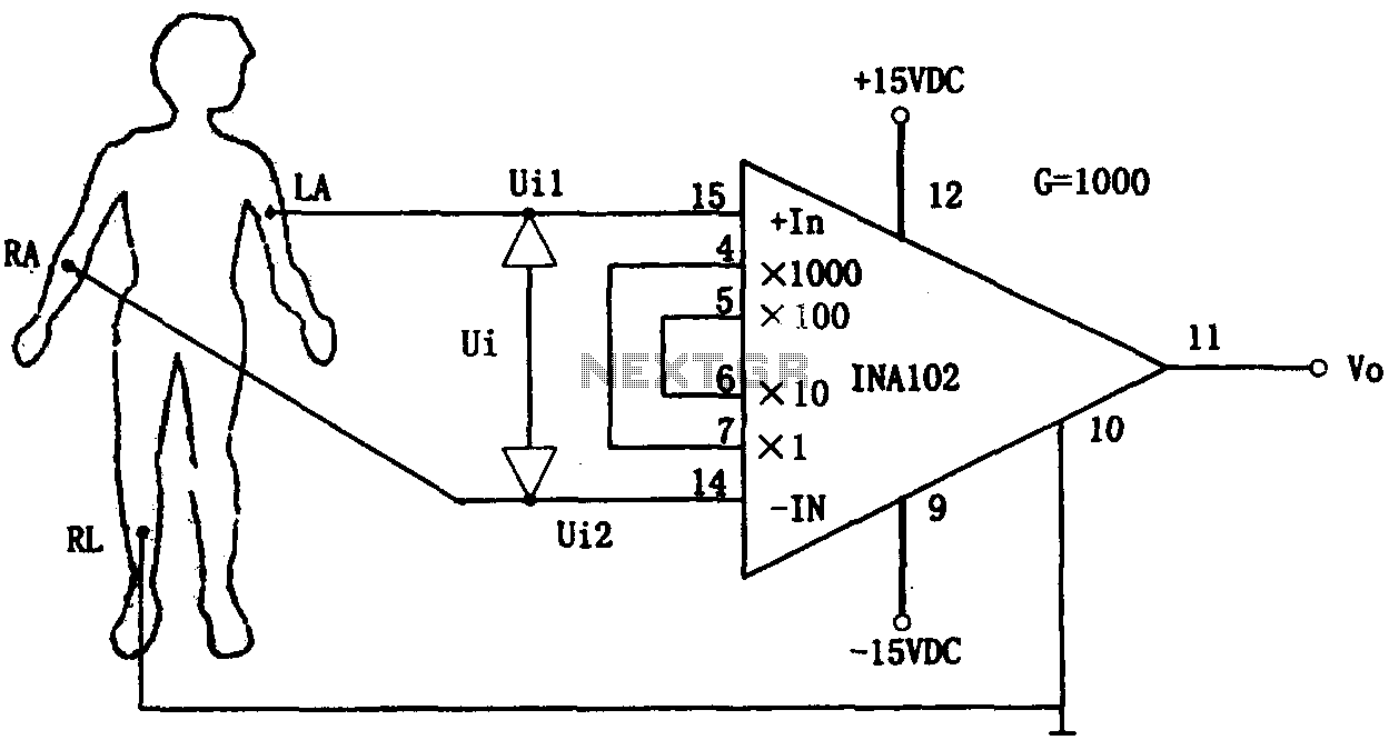
This document outlines a preamplifier circuit designed for measuring human biological signals, such as ECG and EEG. These biological signals are typically weak and require high amplification circuits. The circuit utilizes a low-power integrated operational amplifier, INA102. The INA102...
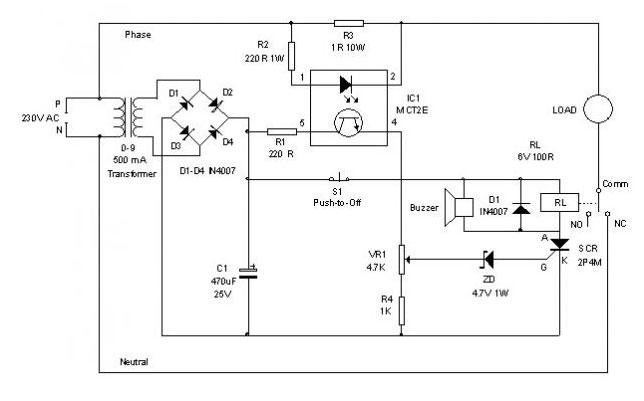
An electronic circuit breaker is designed to detect overload conditions and disconnect power when the load exceeds a predetermined threshold. This circuit is particularly suitable for safeguarding Uninterruptible Power Supply (UPS) devices, such as inverters. The electronic circuit breaker operates...
The circuit of a loop sensor-based simple security alarm is described here. The sensor loop consists of a short length of thin enamelled copper wire. The loop sensor security alarm operates on the principle of detecting interruptions in the circuit...
This transmitter emits an FM signal within the 88 to 108 MHz frequency range, featuring a tone of 19 kHz. This tone can activate the FM MPX pilot carrier indicator, allowing interfacing with external devices. L4 is designed for...
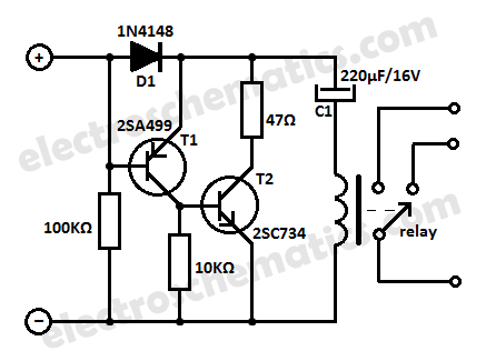
Protect your equipment with this compact 12V time delay relay circuit. The SMPS-based power supply of modern electronic devices is susceptible to voltage spikes. This 12V time delay relay circuit is designed to safeguard sensitive electronic devices by providing a...
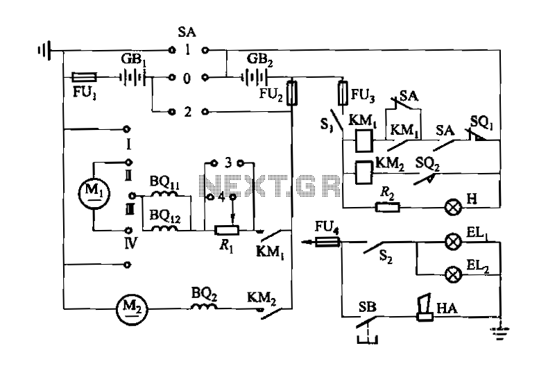
Denote cam controller SA 1 contact closure case. M1 is 1.35 kW driving motor, M2 is a 4 kW pump motor. The circuit involves a cam controller designated as SA 1, which is responsible for managing the operation of...
Warning: include(partials/cookie-banner.php): Failed to open stream: Permission denied in /var/www/html/nextgr/view-circuit.php on line 713
Warning: include(): Failed opening 'partials/cookie-banner.php' for inclusion (include_path='.:/usr/share/php') in /var/www/html/nextgr/view-circuit.php on line 713