
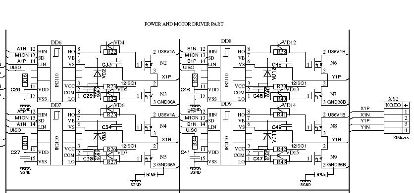
Circuit Diagram Of Motor Control Unit Based On The LM317 IC
The motor control unit circuit utilizes the LM317 voltage regulator to provide a stable output voltage for driving a motor. The LM317 is known for its adjustable output voltage, which can be set using two external resistors. In this configuration, the output voltage can be varied according to the requirements of the motor being controlled.
The circuit typically includes input and output capacitors to ensure stability and reduce noise. The input capacitor helps filter any high-frequency noise from the power supply, while the output capacitor stabilizes the output voltage. Additionally, the inclusion of diodes serves a critical function in protecting the LM317 from voltage spikes that can occur when the motor is switched off or during reverse polarity situations.
In the schematic, the motor is connected to the output of the LM317, and a potentiometer may be used to adjust the resistance, allowing for fine-tuning of the motor speed. The diodes are placed in parallel with the motor terminals, oriented to allow current to flow back into the circuit during the motor's off state, effectively protecting the LM317 from back EMF (electromotive force) generated by the motor.
Overall, this motor control unit circuit provides a reliable solution for controlling motor speed while ensuring the longevity and reliability of the LM317 voltage regulator through adequate protection mechanisms.The following circuit show about Circuit Diagram Of Motor Control Unit. This circuit based on the LM317 IC. Features:diodes protect the regulator, .. 🔗 External reference
Related Circuits
This sensitive touch potentiometer utilizes IC1 (CA3130), an operational amplifier known for its high input impedance. When a finger touches the Se1 sensor, C2... This circuit design incorporates a touch-sensitive potentiometer that leverages the CA3130 operational amplifier to achieve high...
Setting circles on an astronomical telescope are used as an aid to point the telescope at a specific object in the sky based on the object's celestial coordinates. However, setting circles can be challenging to use effectively and are...
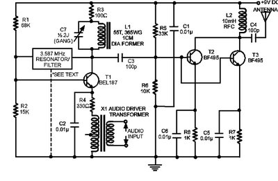
The circuit presented here is a powerful AM transmitter utilizing a ceramic resonator/filter operating at 3.587 MHz. This circuit primarily relies on a transistor for its core functionality. It is possible to use resonators/filters of other frequencies, such as...
The primary application area for brushless direct current motors (BLDC) is in positioning systems. Brushless Direct Current (BLDC) motors are widely utilized in various positioning applications due to their high efficiency, reliability, and precise control capabilities. These motors operate without...
This is a very simple, low-cost, Hi-Fi quality power amplifier. It can be built in five different configurations, as shown in the table, ranging from 20 W to 80 W RMS. The Hi-Fi quality power amplifier circuit is designed to...
A fluorescent tube is connected in an LC resonant circuit consisting of inductor L2 and capacitor C9. The bidirectional breakdown diode VD4 initiates the starting circuit. When AC power is applied, the gate potential of transistor VT2 increases due...
Warning: include(partials/cookie-banner.php): Failed to open stream: Permission denied in /var/www/html/nextgr/view-circuit.php on line 713
Warning: include(): Failed opening 'partials/cookie-banner.php' for inclusion (include_path='.:/usr/share/php') in /var/www/html/nextgr/view-circuit.php on line 713