
Brushless DC electric motor control by CPLD
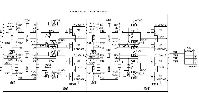
Brushless Direct Current (BLDC) motors are widely utilized in various positioning applications due to their high efficiency, reliability, and precise control capabilities. These motors operate without brushes, which minimizes mechanical wear and enhances longevity. The primary function of BLDC motors in positioning systems includes precise angular positioning, speed control, and torque management.
In a typical positioning system, a BLDC motor is paired with a feedback mechanism, such as an encoder or a resolver, to provide real-time positional data. This feedback loop is essential for maintaining accuracy and ensuring that the motor responds appropriately to control signals. The motor driver circuit, which typically includes a microcontroller or a dedicated driver IC, interprets the feedback signals and adjusts the motor's operation accordingly.
The control strategy for BLDC motors often employs techniques such as Field-Oriented Control (FOC) or trapezoidal control, which optimize performance across a range of speeds and load conditions. Additionally, BLDC motors are favored in applications requiring high dynamic response, such as robotics, CNC machinery, and automated assembly systems, where precise positioning is critical.
In summary, the application of BLDC motors in positioning systems is characterized by their efficiency, durability, and ability to deliver accurate control, making them suitable for a wide range of industrial and consumer applications.The main area for application of brushless direct current motors (BLDC) is positioning 🔗 External reference
Related Circuits
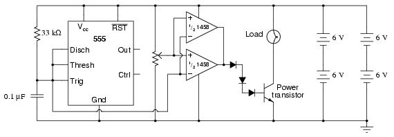
This circuit utilizes a 555 timer to generate a sawtooth voltage waveform across a capacitor, which is then compared to a steady voltage provided by a potentiometer using an operational amplifier (op-amp) configured as a comparator. The comparison of...
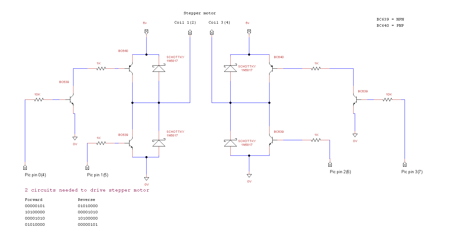
miRover. This page details how to use a PIC microcontroller and an H-bridge or an L298 to drive a bipolar stepper motor. The project involves utilizing a PIC microcontroller to control a bipolar stepper motor, which is commonly used in...
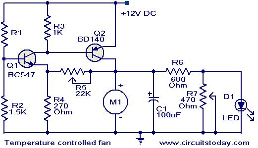
This circuit utilizes two transistors to regulate the speed of a 12 V DC fan based on temperature changes. A thermistor (R1) detects the temperature. As the temperature rises, the base current of transistor Q1 (BC 547) increases, leading...
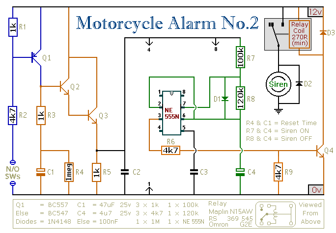
This circuit provides an intermittent siren output with an automatic reset function. It can be manually activated using a key switch or a concealed switch, and it can also be configured to engage automatically when the ignition is turned...
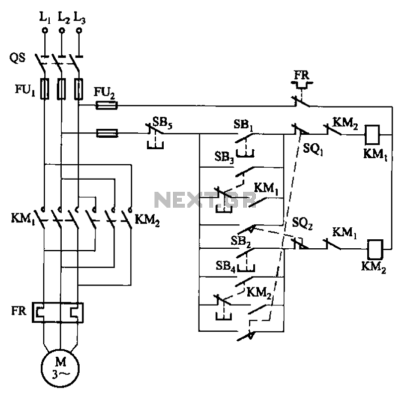
The circuit depicted in Figure 3-27 features a jog function that allows for precise adjustments of moving components. In the figure, SB3 and SB4 represent the forward jog and reverse jog buttons, respectively. When the SB3 button is pressed,...
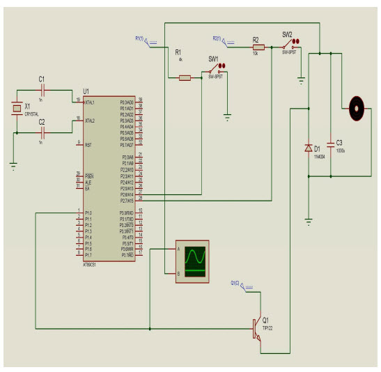
The objective of this project is to control the speed of a DC motor. The primary benefit of utilizing a DC motor is the ability to modify the Speed-Torque relationship to nearly any desired form. To facilitate speed control,...