
Circuit Diagram Of Slave Flash Light Control

The Slave Flash Light Control Circuit is designed to manage the operation of a secondary flash light in conjunction with a primary flash unit. This circuit typically operates on the principle of inductive coupling, where the 68mH inductor plays a crucial role in energy transfer and triggering the secondary flash light.
In this circuit, the primary flash light acts as the main source of illumination, which, when activated, induces a current in the 68mH inductor. This induced current serves to automatically trigger the secondary flash light, allowing it to illuminate shortly after the primary flash. The timing of the secondary flash can be adjusted by modifying the characteristics of the inductor and associated components, such as capacitors and resistors, which may be included in the circuit for timing control.
The design may also incorporate additional features such as a diode for rectification, ensuring that the current flows in the correct direction and protecting against potential back EMF generated by the inductor. A transistor may be used as a switch to control the activation of the secondary flash light based on the signal received from the inductor.
Overall, this Slave Flash Light Control Circuit provides a reliable method for synchronizing multiple flash lights, enhancing photographic applications or emergency lighting systems where additional illumination is required.The following circuit shows about Slave Flash Light Control Circuit Diagram. Features: 68mH Inductor, give auto trigger for secondary flash light, . 🔗 External reference
Related Circuits

The peak voltage sample and hold circuit is illustrated in Figure 12-50. This circuit comprises the LF398 sample and hold chip and the LM311 voltage comparator. The LF398 is responsible for outputting and inputting voltages. The LM311 compares the...
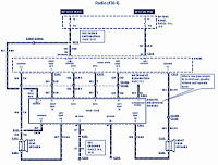
The section of the 1996 Ford Windstar wiring diagram includes details on power distribution, common connections, rear circuits, ignition systems, the fuse panel, battery connections, instrument illumination, radio wiring, left rear speaker connections, remote headphone module, solid-state components, and...
There are numerous used batteries available, primarily AA size, from various electronic devices such as remote controls and cameras. Disposing of these batteries often raises concerns due to their residual charge. While rechargeable batteries are an alternative, they may...
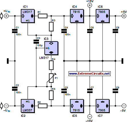
This current-limiting circuit, illustrated in this example as part of a small bench power supply, could theoretically be utilized alongside any dual-rail current source. The section of the circuit to the left of the diagram restricts the input current...
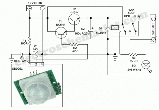
The SB0061 is a pyroelectric sensor module designed for human body detection. It integrates a PIR (Passive Infrared) detector with a Fresnel lens on a compact printed circuit board (PCB), along with an analog integrated circuit (IC) identified as...
Creating circuit boards can be a challenging task. It requires designing a schematic, testing it on a breadboard, laying out the board, and finally printing and etching the board. Fortunately, Fritzing offers a solution. Fritzing is a free, open-source...