
Peak voltage sample and hold circuit
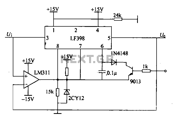
The peak voltage sample and hold circuit functions as a critical component in various electronic systems requiring accurate peak voltage measurements. The LF398 is a versatile sample and hold amplifier that captures the peak voltage levels and maintains them for subsequent processing. The LM311 comparator serves to monitor the input voltage and determine when to switch the LF398 between sampling and holding states.
In operation, the circuit begins with the LM311 continuously comparing the instantaneous input voltage (U) against the held output voltage (Uo). When the input voltage rises and exceeds the previous peak, the LM311's output transitions to a high state, activating the LF398 to sample the new peak voltage. This transition is facilitated by the logic control terminal, which is crucial for determining the operational state of the LF398.
Once the peak voltage is captured, the LM311 monitors for any decrease in the input voltage. If the input voltage falls below the previously held voltage, the LM311 outputs a low signal, which instructs the LF398 to switch to its hold state. In this state, the LF398 maintains the last sampled peak voltage until a new peak is detected.
The use of an open collector output in the LM311 necessitates the inclusion of a pull-up resistor to ensure proper voltage levels are maintained when the output is low. This configuration allows for flexibility in interfacing with other circuit components or logic levels.
Moreover, the overvoltage detection circuit adds an additional layer of functionality, preventing damage to the circuit by controlling the discharge of the sampling capacitor. This feature ensures that the capacitor discharges only under safe conditions, thereby preserving the integrity of the sampled voltage and maintaining the reliability of the circuit's performance.
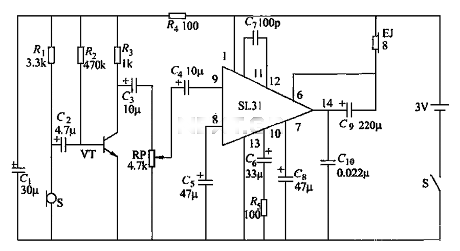
Overall, this peak voltage sample and hold circuit is essential for applications in signal processing, measurement systems, and any scenario where precise voltage tracking is required. Its design effectively balances the need for accurate sampling with protective measures to enhance circuit longevity and reliability.Peak voltage sample and hold circuit: peak voltage sample and hold circuit is shown in Figure 12-50. Peak voltage sample and hold circuit south chip sample and hold chip LF398 and a voltage comparator LM311 constitution. LF398 output and input voltages LM3J1 by comparing t When U. Uo time. LM311 output high, to LF398 logic control terminal 8 feet, LF398 in the sampling state state} When Ul peak and decline, U, <U., Output low voltage comparator LM311, LF398: Logic control terminal set to low level, so LF398 hold. Since the LM311 use open collector output, so an pull-up resistor. By the overvoltage detection circuit output terminal sent pulse control circuit switch is turned on, the sampling capacitor discharges never had electricity, otherwise sampling circuit has been tracking the peak change.
Related Circuits
This is a simple game show timer designed for beginners. The power source can be a standard 12-volt lantern battery or a battery pack made from C or D cells. The lamps used can be regular flashlight bulbs; the...
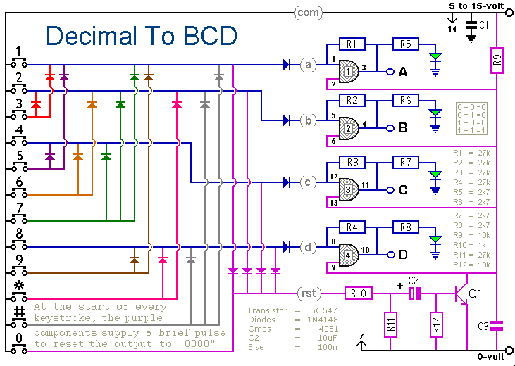
When a keypad switch is pressed, this circuit reproduces its value in Binary Coded Decimal (BCD) format. A 12-keypad is used, but it can be expanded to 16 keys for Hexadecimal to BCD conversion. The circuit consists of two...
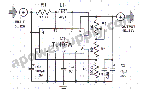
This voltage converter is constructed using the TL497A integrated circuit and is designed to convert an input voltage range of 5 to 12 volts into a higher output voltage range of 15 to 30 volts. This functionality is particularly...
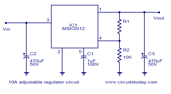
A reliable 10A adjustable voltage regulator based on the MSK5012, featuring an output voltage range of 1.3 to 30V. It is characterized by low ripple and high efficiency. The MSK5012 adjustable voltage regulator is designed for applications requiring a stable...
Bicycle tire leak detector circuit schematic. The circuit detects air leaks in car tires caused by sharp objects. It uses a microphone (BM) to capture the sound of escaping air, which is then converted into an electrical signal. This...
This circuit utilizes a synchronous demodulator to extract a 1 kHz signal from noise and measures its amplitude, with the 1 kHz signal providing a resolution of approximately 60 microvolts per count. The measurements are transmitted via an RS-232...
Warning: include(partials/cookie-banner.php): Failed to open stream: Permission denied in /var/www/html/nextgr/view-circuit.php on line 713
Warning: include(): Failed opening 'partials/cookie-banner.php' for inclusion (include_path='.:/usr/share/php') in /var/www/html/nextgr/view-circuit.php on line 713