
Circuit Enables Single NiMH Cell to Simulate a Lithium Battery

The described circuit effectively provides a solution for utilizing NiMH cells in applications designed for Li+ batteries, addressing both performance and efficiency. The implementation of a burst mode operation minimizes power consumption during inactive periods, while the careful design of feedback and control mechanisms ensures reliable operation across varying voltage levels. The use of an integrator and the configuration of a microprocessor supervisor facilitate precise voltage monitoring and control, enhancing the circuit's adaptability to different load conditions. The overall design highlights the importance of balancing performance requirements with power management, making it suitable for applications where battery life is critical. The addition of a charging interface for Li+ batteries could further enhance the circuit's versatility, enabling seamless integration into existing systems.Lithium-based (Li+) batteries are becoming common in portable equipment. They have desirable characteristics, but they are often in short supply. Lead times can be long unless you have a preferred-customer status with the battery manufacturer. A backup alternative to Li+ is therefore desirable, especially for smaller companies. This note describes a circuit that allows a nickel-metal hydride (NiMH) cell to be used in a circuit designed for a Li+ battery. It provides the same performance, size, and cost as a Li+ battery. A circuit that interfaces a NiMH battery with a lithium-optimized circuit should mimic the battery`s terminal voltage, which declines as the battery discharges.
The nominal terminal voltage for Li+ batteries (3. 6V) is about three times that of NiMH batteries (1. 2V). As a simple approach, therefore, you can force the output of an efficent step-up converter to equal battery voltage times 3: 6V/1. 2V = 3. Allowing the circuit to run constantly during shutdown, however, consumes unnecessary power. The NiMH circuit`s equivalent leakage (its quiescent current) can be as a high as 200 µA during shutdown, which is unacceptable.
In fact, only a power-control capability is needed during shutdown. Instead of maintaining 3x the NiMH voltage while in shutdown, you can run the proposed circuit in burst mode, which activates the step-up converter only when the circuit output drops below a defined threshold. When the output reaches the upper threshold, the step-up shuts down, allowing the output capacitor to discharge through the output load plus the NiMH circuit.
Thus, the output voltage forms a sawtooth wave. If battery voltage falls below a lower limit, however, the circuit remains deactivated to protect the battery from depletion. The circuit of Figure 1 implements the above ideas by providing an interface between a NiMH battery and a lithium-optimized power-management circuit.
The MODE input controls the circuit; HIGH gives the sawtooth, and LOW gives 3*VBATT. The integrator-connected op amp multiplies the battery voltage by driving U1`s feedback node to produce an output three times that voltage (Figure 2). A large integrator time constant is necessary both to avoid interaction with U1`s internal error comparator, and to provide noise filtering.
In low-power mode, a microprocessor-supervisor IC (U2) monitors the output voltage and controls U1. The resistor string associated with U2 sets approximate 2. 4V and 4V thresholds for that device. Finally, the step-up converter must always be shut down when battery voltage drops below a threshold, which is usually 0. 9V. That shutdown is accomplished by the converter`s own internal comparator; the Tiny Logic network selects the correct operating mode according to the state of the MODE control input, the ramp threshold detector (U2), and U1`s internal battery comparator.
To ensure startup from 1. 0V when the output is 0V, the logic network must be supplied directly from the battery. The logic family shown (ULP) functions down to 0. 9V; below 0. 9V, the battery is nearing depletion. Using the components as shown, the sawtooth duty cycle of this circuit is 10% (Figure 3). Note that the circuit has a potential lockup state. When running in sawtooth mode, U2`s upper threshold must always be less than U1`s maximum output. Otherwise, U2 does not shut down U1. U1`s maximum output is set by the R9-R10 resistor string at its FB node. (Because the op-amp output is at high impedance in low-power mode, it does not pull current from the node). This proposed circuit does not include an interface for Li+ battery charging. That function can be implemented with a p-channel MOSFET in series with the charger and the battery, plus the addition of an op amp to servo the charger side of the MOSFET to 3*VBATT.
🔗 External reference
Related Circuits
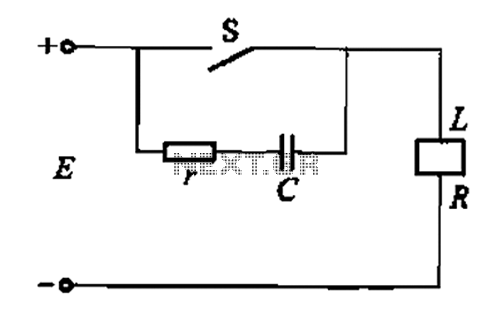
A resistor-capacitor circuit designed to prevent spark blowout. The coil's magnetic energy is converted into electrical energy stored in the capacitance C, effectively suppressing sparks and enhancing safety. The circuit is capable of functioning normally even with reverse polarity....

This circuit represents a remote control unit that utilizes radio frequency signals to operate various electrical appliances. The remote control unit features four channels, which can be expanded to twelve. This circuit stands out from similar designs due to...
The BFP640 transistor is utilized for 1575 MHz Global Positioning Satellite (GPS) applications, specifically as a Low Noise Amplifier (LNA). The design objectives include a minimum gain of 16 dB, a noise figure of less than 0.6 dB, an...
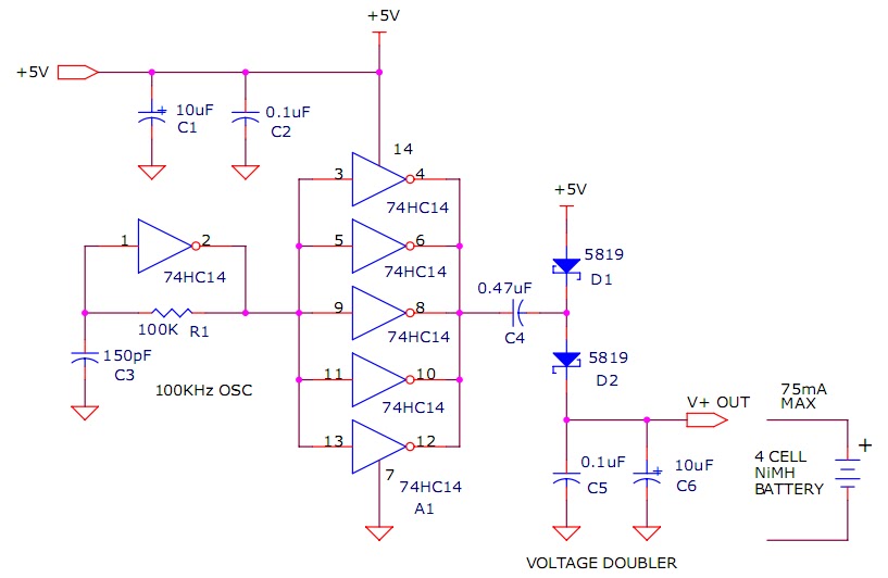
The circuit described will trickle charge a four-cell pack of AA or AAA NiMH batteries. It draws current from the +5V available from a USB connection and supplies approximately 70mA of current to the battery. This current level is...
This is an efficient 4-stage stabilized power supply unit designed for testing electronic circuits. It delivers well-regulated and stabilized output, which is crucial for most electronic circuits to function correctly. The circuit includes an audio-visual indicator that activates in...
A car battery deteriorates with use, typically lasting no more than four years. Initially, its voltage may drop to just 2V when cranking the engine. As the battery ages, its internal impedance increases, leading to a higher voltage drop...
Warning: include(partials/cookie-banner.php): Failed to open stream: Permission denied in /var/www/html/nextgr/view-circuit.php on line 713
Warning: include(): Failed opening 'partials/cookie-banner.php' for inclusion (include_path='.:/usr/share/php') in /var/www/html/nextgr/view-circuit.php on line 713