Car Battery Failure Detector
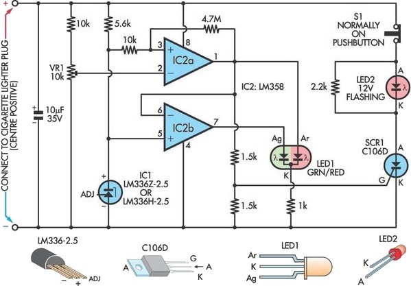
A car battery deteriorates with use, typically lasting no more than four years. Initially, its voltage may drop to just 2V when cranking the engine. As the battery ages, its internal impedance increases, leading to a higher voltage drop during cranking, which can eventually prevent the engine from starting. This gradual increase in voltage drop while cranking serves as an early warning of potential battery failure. Consequently, this circuit activates an alarm when the battery voltage drops to 8V during cranking. IC1 functions as a precision 2.5V reference for two comparators incorporated within IC2, an LM358 dual operational amplifier. IC2a monitors the voltage from trimpot VR1, where its output at pin 1 remains low under normal conditions, while IC2b's output remains high, illuminating LED1 in green. When the voltage at pin 2 of IC2a falls below that at pin 3, its output at pin 1 transitions high, activating the red section of LED1 to signal a fault. Concurrently, IC2b inverts the signal from pin 1, causing its output at pin 7 to go low and extinguishing the green section of LED1 to further indicate a fault. Given that the battery voltage drop occurs briefly during cranking, a more persistent indication of the fault is provided by flashing LED2. When the output of IC2a goes high momentarily, the SCR is latched, causing LED2 to flash, which can only be deactivated by pressing pushbutton S1.
This circuit design utilizes a dual operational amplifier configuration to monitor the voltage levels of a car battery during cranking conditions. The operational amplifier IC2, specifically the LM358, is chosen for its low input offset voltage and ability to operate at a wide supply voltage range, making it suitable for automotive applications.
The circuit begins with a voltage reference established by IC1, which provides a stable 2.5V reference. This reference voltage is critical for accurate comparison and detection of the battery voltage drop. The trimpot VR1 allows for fine-tuning of the voltage threshold that will trigger the alarm, offering flexibility based on specific battery characteristics or user requirements.
IC2a is configured as a non-inverting comparator, comparing the voltage from the battery (through VR1) against the reference voltage. Under normal conditions, the battery voltage is above the threshold, resulting in a low output from IC2a (pin 1). This state keeps the green section of LED1 illuminated, indicating that the battery is functioning properly.
When cranking the engine, if the battery voltage drops below 8V, the output of IC2a transitions high, indicating a fault condition. This change in output drives the red section of LED1, signaling a critical warning to the user. Simultaneously, IC2b, configured as an inverting comparator, reacts to the output of IC2a by turning off the green LED segment, thus providing a dual visual indication of the fault condition.
To ensure that the fault indication persists beyond the transient voltage drop experienced during cranking, an SCR is incorporated into the circuit. When the output of IC2a goes high, the SCR is triggered and latches, causing LED2 to flash. This feature provides a more noticeable alert that can help prevent battery failure by prompting the user to take action. The circuit also includes a pushbutton switch, S1, which allows the user to reset the alarm and turn off the flashing LED2, thereby managing the fault indication effectively.
Overall, this circuit not only enhances the reliability of automotive battery monitoring but also contributes to proactive maintenance, potentially extending the life of the battery and preventing inconvenient failures.A car battery deteriorates in use and its life seldom exceeds four years. When new, its voltage may drop to only 2V while cranking the engine. As the battery ages, its internal impedance increases and so the voltage drop while cranking also increases, until ultimately the drop is high enough to prevent the engine from starting. This gradual increa se in voltage drop while cranking can be used as an early warning of looming battery failure and so this circuit triggers an alarm when the battery voltage drops to 8V during cranking. IC1 is a precision 2. 5V device used as the reference for two comparators based on IC2, an LM358 dual op amp. IC2a monitors the voltage from trimpot VR1 and normally its output at pin 1 will be low while the output of IC2b will be high and LED1 will be green.
When pin 2 of IC2a falls below pin 3, its output at pin 1 will go high to drive the red section of LED1 to indicate a fault. At the same time, IC2b inverts the signal from pin 1 and its output at pin 7 goes low and turns off the green section of LED1 to indicate a fault.
Since the battery voltage drop occurs momentarily while cranking, a more permanent indication of the fault is provided by flashing LED2. When IC2a`s output goes high momentarily, the SCR is latched and LED2 flashes and can only be deactivated by pressing pushbutton S1.
🔗 External reference

