
144MHz All Mode Transceiver
The transceiver circuit is designed to operate efficiently while maintaining ease of assembly and low cost. The MC3362 integrated circuit serves as the heart of this design, combining multiple functions into a single chip. The RF amplifier, represented by T1, is critical for ensuring that weak signals can be effectively processed, providing a sensitivity of 0.2 µV at the antenna port. This level of sensitivity is essential for reliable reception of weak signals in various operating conditions.
The internal voltage-controlled oscillator (VCO) is a key component that enables frequency modulation. The design allows for frequency tuning through either a phase comparator or a potentiometer, although the latter may introduce some instability. The output from the VCO is robust enough to drive the TX mixer, facilitating efficient transmission.
The use of the 10.7 MHz crystal filter is crucial for both RX and TX modes, as it allows for the selective filtering of signals, thereby enhancing the quality of reception and transmission. The MC1496 integrated circuit plays a dual role in the design, functioning as both a product detector and a balanced modulator, which simplifies the overall architecture and reduces component count.
For audio processing, the LF356 serves as a microphone amplifier, ensuring that audio signals are adequately amplified before transmission. The LM-386 is employed as an audio power amplifier, which provides sufficient output power for driving speakers or headphones.
The synthesizer board, with its variable oscillator, allows for precise frequency control and stability. The ability to select harmonics of the crystal frequency expands the operational range of the transceiver, enabling it to cover different frequency bands effectively.
Overall, this transceiver design exemplifies a balance between simplicity and performance, making it suitable for various applications in amateur radio and other communication systems. The integration of multiple functions within a single IC streamlines the design process, reduces the number of external components required, and ultimately lowers production costs while maintaining high-quality performance.The main characteristic of the transceiver presented below is the simplicity, but in the same time giving good performance, with a minimum investment. The radio is based on MC3362 ( buy ). This integrated circuit its an FM receiver, double conversion, which have inside almost everything that you need to build a radio.
Starting with an RF amplifier and ending with an FM demodulator. Including a VCO up to 180MHz, LO for 10. 245Khz, two mixers, IF amplifiers. Using T1 in the front-end the sensitivity will be 0. 2uV/50ohms at the antenna port. On the RX path, the signal is amplified by T1 and foreword to the pin 1 of MC3362. The voltage control of the internal VCO is pin 23, voltage that must not be higher than Vcc of the MC3362, in our case +5V. The VCO voltage control could be given by a Phase Comparator part of a synthesizer, or could a tuning potentiometer.
Of course, in the last case the frequency stability is not the best. At pin 20 of MC3362 (VCO out) we have 300mV of RF, enough to drive the TX mixer (gate 2 of T9). FM audio is on pin 13. From pin 19 we pick-up the signal for SSB and CW. The filter on this path is a 10. 7MHz Crystal Filter. T5 and T6 are IF amplifiers. MC1496 ( Digi-Key ) is the product detector in RX and DSB balanced modulator in TX mode. For CW carrier this modulator becomes an unbalanced modulator using a DC voltage +TX/CW. The 10. 7MHz crystal filter is used also in TX/SSB to attenuate one of the side bands. T5 is the carrier LO and T8 is the FM modulator. The 3W TX output is obtained using a BLX-65. For microphone amplifier we use an LF 356 and for audio power amplifier LM-386. The variable oscillator (synthesizer board) working in a range of 1 to 3 MHz. Using a 44. 1MHz crystal (T15) we can select the third harmonic (132. 3MHz) which is mixed with VCO signal, and become an RF signal in a range of 1 to 3MHz. This together with VFO output, are applied to the input of the Phase Comparator CD4046 ( Digi-Key ). The error voltage (pin 13 of CD4046) is the voltage control of the internal VCO of MC3362. To display the working frequency we can use the output of the VCO (pin 20 of MC3362) or VFO output (pin 10 CI-6). 🔗 External reference
Related Circuits
The TEA5711 is a high-performance Bimos integrated circuit designed for use in AM/FM stereo radios. It integrates all necessary functions, including the AM and FM front-end, AM detector, and FM stereo output stages. The TEA5711 is engineered to provide a...
A small amplifier IC circuit has been compiled. This circuit is part of an older series and is categorized as a simple OTL (Output Transformer-Less) circuit. The presented small amplifier IC circuit is designed for applications where compact size and...
ISL83202IPZ is a subpackage of ISL83202. For the full description, please refer to ISL83202. The datasheet for ISL83202IPZ can be downloaded from the link provided below. By Intersil Corporation. The ISL83202IPZ is a component within the ISL83202 series, designed for...
This circuit employs an 87C57 microcontroller along with several peripherals to convert X-10 power-line carrier-code formats from a personal computer for use with an X-10 power-line interface in a home-control system. Software details can be found in the reference. The...
The circuit is designed to fit into a small enclosure that can be placed in a backbox at a location of your choice. It requires only three wires: one for the battery positive voltage, one for the +5 volts...
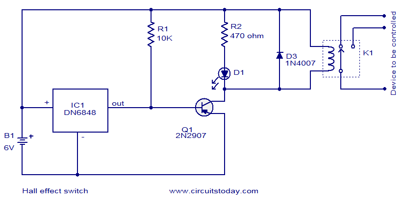
The circuit diagram presented is for a Hall Effect switch. The core component of this circuit is the Hall Effect sensor IC DN6848 from Panasonic. This integrated circuit features a Hall Effect sensor, a Schmitt trigger circuit, a power...