
POWER LINE MODEM FOR COMPUTER CONTROL

The circuit is centered around the 87C57 microcontroller, which serves as the primary processing unit. This microcontroller is capable of executing the necessary algorithms to interpret and format the power-line carrier codes received from a personal computer. The X-10 protocol is a widely used standard for home automation, allowing devices to communicate over the existing electrical wiring in a home.
To facilitate the conversion process, the circuit includes several key peripherals. These may consist of signal conditioning components, such as operational amplifiers or filters, to ensure that the signals are clean and within the required voltage levels for transmission. Additionally, a level shifter may be implemented to interface the microcontroller's logic levels with the higher voltage levels of the power line.
The microcontroller is programmed with specific firmware that handles the encoding and decoding of the X-10 signals. This firmware can be customized to accommodate different device commands, such as turning lights on or off, adjusting dimmer settings, or querying the status of various appliances.
The output of the microcontroller connects to the X-10 power-line interface, which modulates the conditioned signals onto the electrical wiring. This interface is crucial for ensuring that the commands sent from the personal computer can be effectively transmitted to and understood by X-10 compatible devices throughout the home.
Overall, this circuit design provides a robust solution for integrating a personal computer with an X-10 home-control system, enabling automated control of various household devices through a user-friendly interface.This circuit uses an 87C57 microcontroller and a few peripherals to condition X-10 power-line carrier-code formats from a personal computer to use an X-10 power-line interface in a home-control system. Software details are available in the reference.. 🔗 External reference
Related Circuits
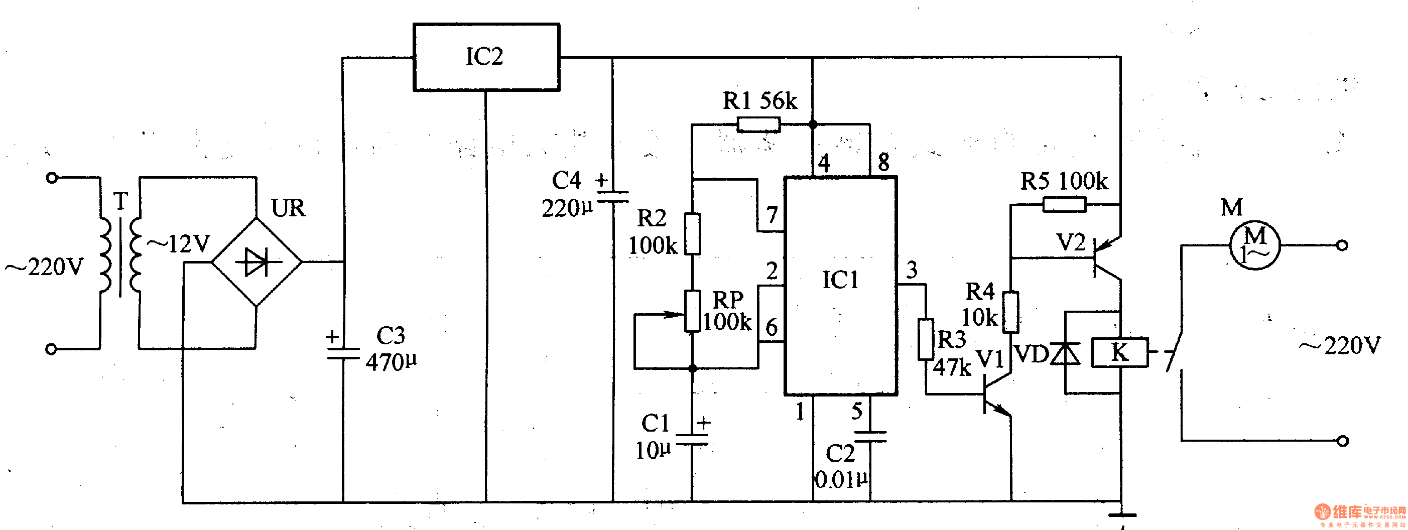
The medical ventilator controller circuit consists of an astable oscillator, a control circuit, and a power supply circuit. The astable oscillator is constructed using resistors R1, R2, a potentiometer RP, capacitors C1, C2, and a time base integrated circuit...
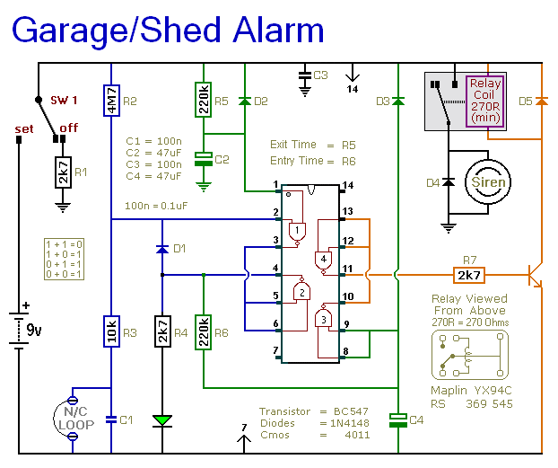
The following circuit illustrates a 9V power supply for a garage shed alarm circuit diagram. Features include a single-zone burglar alarm circuit that is used with the system. The 9V power supply circuit for the garage shed alarm is designed...
This analog switch utilizes the 2N4860 JFET, which features a low on-resistance (rON) of 25 ohms and minimal leakage current. The LM102 acts as a voltage buffer in the circuit. It is designed to be adaptable for use in...
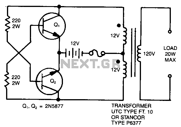
A simple 120 V to 24 V center-tapped control transformer, along with four additional components, can accomplish the task. This circuit produces a clean 200 V peak-to-peak square wave at 60 Hz and is capable of supplying up to...
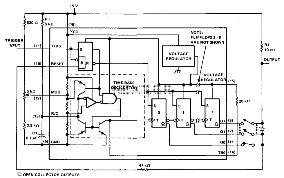
The µA2240 can be easily configured as a programmable voltage-controlled timer with a minimal number of external components. The modulation input (pin 12) allows for external adjustment of the input threshold level. A variable voltage is applied from the...
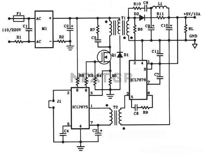
The following diagram illustrates a 50W offline switching power supply circuit design. This circuit is powered by a MOSFET, specifically the BUZ80A/IXTP4N8 for a 220V AC voltage input and the GE IRF823 for a 110V AC voltage input. The...