
Cable TV amplifier Using 2 Transistor

The cable TV amplifier circuit consists of two main components, T1 and T2, both of which are crucial for enhancing the signal strength of the incoming cable TV signal. The first transistor, T1, is configured in a common emitter mode, which allows it to amplify the voltage of the signal. The expected gain of 20 dB indicates that the output signal will be significantly stronger than the input, making it suitable for compensating for signal losses that may occur over long coaxial cable runs.
T2, the second transistor, is configured as an emitter follower. This configuration is important as it provides a high input impedance and a low output impedance, effectively isolating the previous stage from the load. This helps to ensure that the amplification provided by T1 is not adversely affected by the subsequent stages of the circuit or by the load connected to the output. The emitter follower configuration also maintains the voltage level while allowing for a higher current output, which is beneficial for driving loads such as television receivers or further amplification stages.
The circuit is designed to operate within the frequency range of up to 150 MHz, making it suitable for most standard cable TV signals. The use of 75 Ohm coaxial cables is standard in cable television systems, and the amplifier is optimized for this impedance to ensure maximum power transfer and minimal signal reflection.
Overall, this cable TV amplifier circuit is a practical solution for enhancing signal strength in cable television systems, ensuring clear and reliable reception across a range of frequencies. Proper implementation of the circuit with appropriate power supply and layout considerations will maximize performance and reliability.This is cable TV amplifier using 2 transistors. This amplifier circuit is for cable TV systems using Ohm coaxial cables and works fine up to 150MHz. Transistor T1 performs of amplification. Up to 20dB gain expected from the circuit. T2 is wired as an emitter follower current gain. 🔗 External reference
Related Circuits

Useful circuit for self-powered speakers, radios, and TVs; can be used as a car power amplifier. Here is the schematic for an 8-watt audio power amplifier. The described circuit serves as an 8-watt audio power amplifier, suitable for various applications,...
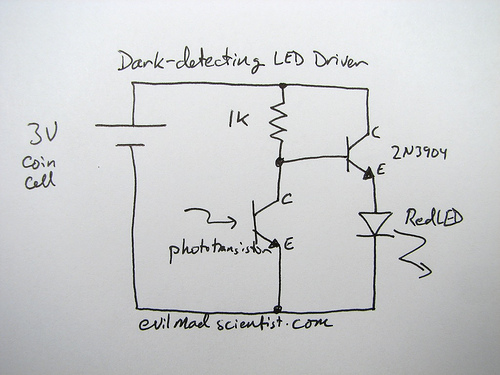
The following circuit illustrates a simple and inexpensive dark-detecting LED circuit. Features include the use of photoresistors, specifically a photocell or LDR, and an LED. This circuit utilizes a light-dependent resistor (LDR) as the primary sensing element. The LDR exhibits...
The following circuit illustrates a Power Amplifier Circuit Diagram utilizing a 2N3055 transistor. Features include a 500-ohm current and an optimal voltage of 50V. The power amplifier circuit based on the 2N3055 transistor is designed to deliver significant output power,...
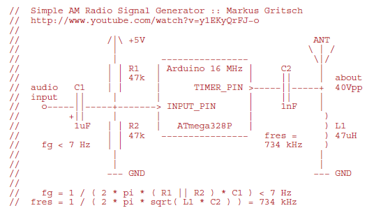
Markus constructed a software AM radio transmitter utilizing an Arduino. The audio signal is supplied to the ADC input via a decoupling capacitor. A PWM output pin directly controls a capacitor-inductor circuit connected to an antenna. The schematic and...
Christmas is approaching, and it is the time of year when electronics students and hobbyists consider creating a Christmas circuit for their homes, particularly one that features flashing lights. Numerous circuits and kits are available that can flash various...
A 24V DC power supply circuit utilizing the LM7824 integrated circuit (IC). The LM7824 is a fixed output voltage regulator IC that provides 24V at a maximum current of 1.5A and is available in a TO-220 package. It is...