
Light Follower Robot using Arduino
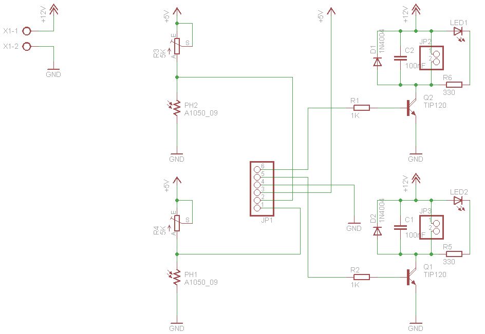
In the circuit on the left, the LED remains off due to the high resistance of the LDR without light, keeping the transistor in a cut-off state. When light is directed onto the LDR, its resistance decreases, resulting in base polarization that allows the transistor to conduct and turn the LED on. Conversely, in the circuit on the right, the LED is initially on because the LDR's resistance exceeds the combined resistance of a 10KΩ resistor and a 10KΩ potentiometer, thus polarizing the transistor and driving the LED. When light falls on the LDR, its resistance drops, leading to a reduction in current that turns the transistor off, switching the LED off. In the BUGBot design, DC motors are employed to control the transmission system (including the gearbox and wheels), enabling the robot to follow the light detected by the sensors. Merely detecting light and toggling the motors on or off is insufficient; the motors must be powered for a minimum duration to ensure proper operation. For the motor driver, which only requires unidirectional rotation, an H-bridge is unnecessary; instead, Darlington transistors can be utilized effectively.
The described robotic system leverages the Arduino platform as a central processing unit, orchestrating the interactions between various components. The LDRs serve as critical input devices that detect light intensity, providing feedback to the Arduino for decision-making. The varying resistance of the LDRs, influenced by light exposure, allows for precise control of the robot's behavior.
The implementation of transistors in the circuit is essential for controlling the LED indicators based on the light detected by the LDRs. The use of Darlington transistors in the motor driver circuit simplifies the design while ensuring efficient control of the DC motors. The configuration allows for effective operation without the complexity of an H-bridge, making it suitable for applications where motors are required to run in a single direction.
The overall circuit design integrates the sensors, processing unit, and actuators to create a responsive robotic system capable of light-following behavior. The motors' control strategy, which includes maintaining power for a sufficient duration, ensures that the robot can navigate its environment effectively. This design exemplifies the intersection of sensor technology, microcontroller programming, and motor control in robotics, providing a foundational understanding for further advancements in robotic applications.The figures above shows the basic idea of any robot, where we have some inputs and output devices connected to the brain and some outputs controlled by the brain. In our case we will have the Arduino like the brain. The central Brain, controls all movements of the Robot. The sensors will do the monitoring where the light focus is and finally the m otors that gives to the robot its movements to go forward, to turn left and to turn right. The input devices will be LDRs (Light Dependent Resistor) those components have its resistance changed according to the incidence of light on the device. Basically, if there is no incident light, the LDR will have a high resistance (from 200K © to 5M © more or less), and when the incidence of light the LDR will have a reduced resistance (since some dozens of ohms to rough a few hundreds) as we can see in the LDR`s characteristic curve above In the circuit on the left, initially we can note that the LED is off because the resistance of the LDR without incident light, let the transistor in cut state.
When we line up the light focus on the LDR, it will decrease its resistance and thus we have a base polarization, and so the transistor enter in the conducting state, switching the LED on. In the circuit on the right, we will notice that the LED is initially in the state on, since we have no incident light on the LDR and the LDR have a resistance greater than the sum of resistances of the resistor of 10K + the 10K potentiometer; the transistor base will be polarized driving the LED, and when the light falls on the LDR, the LDR will have a decrease in current and will sustain the transistor into the cut state switching the LED off.
In our BUGBot, we use DC motors to control transmission system (gearbox and wheels) so that the robot can move and so follow the incident light on the sensors. It is not sufficient only to detect the presence of light on the sensors and drive the motors on/off, the motors must also keep powered by an amount of time for minimum operation.
For the motor driver (as they must rotate only in one direction), it is not necessary to use an H-bridge, we can do the motor driver using only Darlington transistors. 🔗 External reference
Related Circuits

This Arduino-based project involves constructing a lamp with various light displays, including a color sequencer, dimming light, color chaser, and firelight, all controlled by a touch bar on the circuit board. The design adopts a minimalist approach, incorporating only...

3 to 12 volts step-up DC converter using MAX668 integrated circuit design The circuit described is a step-up (boost) DC-DC converter designed to convert an input voltage in the range of 3 to 12 volts into a higher output voltage....
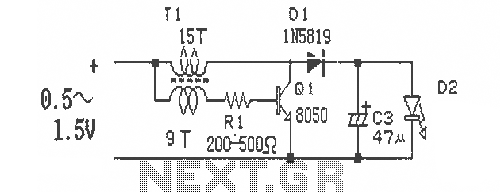
This is a simple and easy-to-build DC-DC driver circuit designed for a single flashlight battery, operating at a parametric voltage of 1.5V. The input current is 90mA, while the light-emitting diode (LED) current is 26mA or higher. The circuit...
Pulse position modulation is similar to pulse width modulation, but the frequency is not constant. Like pulse width modulator circuit, pulse position modulation... Pulse Position Modulation (PPM) is a modulation technique in which the position of a pulse within a...
There are numerous used batteries available, primarily AA size, from various electronic devices such as remote controls and cameras. Disposing of these batteries often raises concerns due to their residual charge. While rechargeable batteries are an alternative, they may...
Any type of flashing light on the main brake lights is prohibited and illegal in most states of the U.S.A. Verification is being conducted for the same in Canada. Meanwhile, using this circuit is at one's own risk, with...