
Simple condenser microphone circuit Schematic Diagram
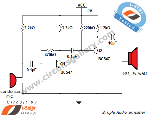
The described circuit represents a simple condenser microphone configuration, where the condenser microphone converts sound waves into an electrical signal. The initial signal is coupled through a 0.1 µF capacitor, which blocks any DC offset, allowing only the AC audio signal to pass through. This is crucial for audio applications, as DC components can interfere with the desired audio signal.
Transistor Q1 operates in a collector-to-base configuration, a common setup for amplifying weak signals. The 470kΩ resistor connected to the base of Q1 plays a vital role in establishing the biasing point of the transistor, ensuring it operates in the active region for optimal amplification. The negative feedback provided by this resistor stabilizes the gain of the transistor, making the circuit less sensitive to variations in temperature and transistor parameters.
The output from Q1 is taken from the collector, where a 3.3kΩ resistor is connected. This resistor is essential for determining the output impedance and plays a role in the overall gain of the circuit. The signal at the collector is then fed into transistor Q2 through another 0.1 µF coupling capacitor. This second capacitor serves a similar purpose as the first, ensuring that the DC biasing of Q1 does not affect the input to Q2.
Transistor Q2 further amplifies the audio signal, which can then be processed or sent to additional circuitry for further amplification or signal conditioning. The overall design of this microphone circuit emphasizes simplicity and efficiency, making it suitable for various audio applications where compactness and reliability are essential. The use of coupling capacitors at both stages is a standard practice in audio signal processing, ensuring that the integrity of the AC signal is maintained while removing any unwanted DC components.The output of condenser mic is coupled via a coupling capacitor of 0. 1 µF, the purpose of this capacitor is to remove DC contents in the audio signal. Transistor Q1 is configured as collector to base biasing mode. This is accomplished via 470k © resistance. This resistor provides negative feedback to the transistor Q1. The output of Q1 becomes a vailable at the collector (across 3. 3k © resistor), which is the input to the transistor Q2 via a 0. 1 µF capacitor. The capacitor removes DC voltages due to the biasing of Q1. You are reading the Circuits of Simple condenser microphone circuit And this circuit permalink url it is 🔗 External reference
Related Circuits
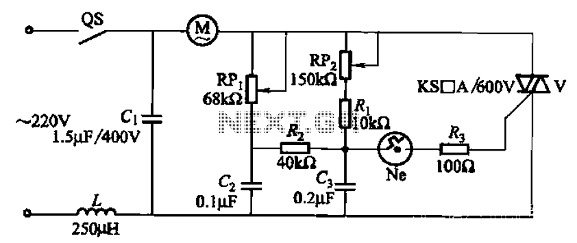
The 3P10 circuit, illustrated in the figure, utilizes a bidirectional thyristor for control. The adjustment potentiometer RPi allows for modification of the minimum motor speed, while the adjustment potentiometer RP2 enables continuous variation of the motor speed, reaching up...
This is a simple yet effective darkness activator. It uses a light-dependent resistor (LDR) to detect light, and when no light is present, it activates an alarm from an 8-ohm speaker. The circuit can be easily modified to function...
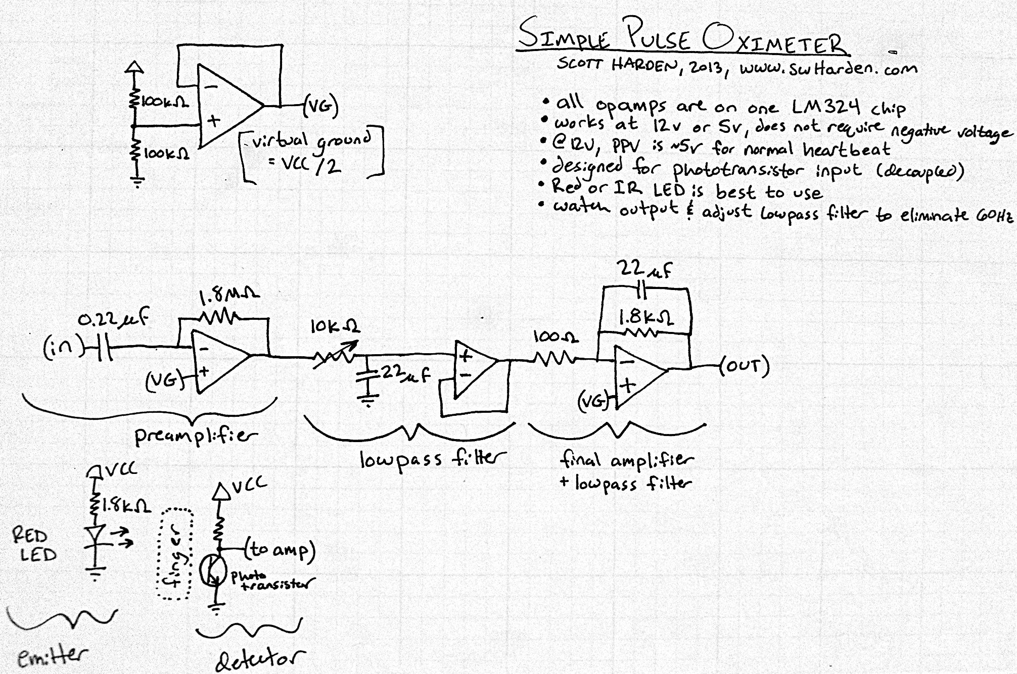
The input capacitor for the phototransistor at the bottom is responsible for feeding the operational amplifier (op-amp). However, the output from the phototransistor consistently remains between ground (GND) and the supply voltage (Vcc). The necessity for an input capacitor...
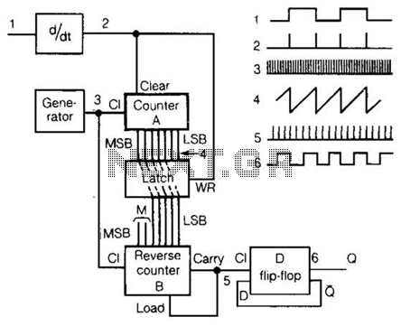
An input rectangular signal is differentiated to produce short impulses from its edges. These impulses transfer the content of counter A to a latch that clears the counter after a very brief period. Counter A counts impulses at a...
The MAX1896, MAX1973, and MAX8863 are integrated circuits that provide output voltages of 5V at 225mA, 1.8V at 220mA, and 3.3V at 60mA, sourced from a USB port. USB devices typically draw power with a voltage range of 4.5V...
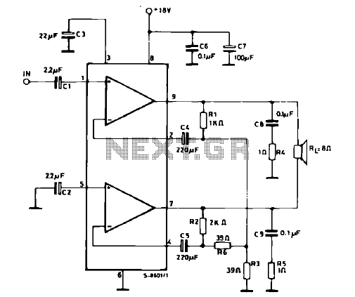
The schematic illustrates a 12 W Bridge Amplifier circuit diagram utilizing the TDA2007A, a class AB dual audio power amplifier. This amplifier is specifically designed for stereo applications in music centers, television receivers, and portable radios. As stated in...