
Pulse meter circuit

The circuit design features a phototransistor connected to an operational amplifier, where the phototransistor serves as a light sensor that responds to variations in light intensity. The input capacitor connected to the phototransistor plays a critical role in ensuring that only the alternating current (AC) components of the signal are fed into the op-amp, effectively blocking any direct current (DC) bias that may distort the signal. This bias can arise from ambient light, which may inadvertently cause the phototransistor to operate in a partially conductive state, resulting in unwanted DC levels that obscure the desired AC signal.
The operational amplifier is configured in a non-inverting mode, utilizing a large feedback resistor to achieve substantial gain. This configuration is essential for amplifying the minute variations in light detected by the phototransistor, particularly those changes associated with physiological signals such as heartbeats. The AC coupling capacitor ensures that the op-amp can function within its linear range, allowing it to amplify small signal fluctuations without being affected by the DC bias.
In scenarios where the virtual ground is not employed, or if a bipolar supply is used, the importance of the AC coupling capacitor remains unchanged. It is vital for maintaining signal integrity and ensuring that the op-amp can effectively amplify the small AC signals generated by the phototransistor. The overall circuit design emphasizes the importance of careful component selection and configuration to achieve reliable and accurate signal amplification in the presence of varying ambient light conditions.The input cap for The phototransistor at the bottom is what feeds the opamp. But the output from the phototransistor is always between GND and Vcc. So why the need for an input capacitor It`s most likely there because the photo transistor is not being switching fully on and off. It is likely giving a very small "wiggle" in response t o the small change in transmitted light during a heartbeat. The first op amp stage is configured for a lot of gain with that large feedback resistor. The AC coupling allows the feedback to establish a linear operation point for the first stage to amplify the small blips from the phototransistor. while I kinda agree that it`s probably needed to isolate it from the virtual ground, that`s not the only reason.
For example, if you removed the virtual ground and powered the circuit with a bipolar supply, you would still need the AC coupling capacitor. for the reasons stated by w2aew. The ambient light is going to bias the transistor on in a small linear region. w2aew described it just about perfectly, it will be like little wiggles on the DC level, probably just a few microvolts, and the AC input capacitor will remove this BIAS caused by the LED and allow the signal to be amplified.
🔗 External reference
Related Circuits
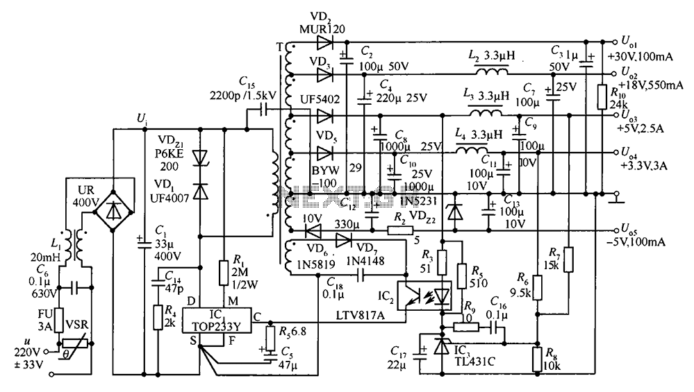
A 35W switching power supply circuit designed for a set-top box output is depicted in Figure 5. It features five distinct voltage outputs: Uo1 (+30V, 100mA), Uo2 (+18V, 550mA), Uo3 (+5V, 2.5A), Uo4 (+3.3V, 3A), and Uo5 (-5V, 100mA)....
This solid-state push-pull single-ended Class A circuit is designed to deliver sound quality comparable to valve amplifiers, providing an output power of 6.9W measured across an 8 Ohm loudspeaker cabinet load. It features reduced total harmonic distortion (THD), increased...

There are instances when it is necessary to view video clips captured by a digital camera on a television. This can be accomplished by connecting the camera's video output to the television's video input. However, a direct connection is...
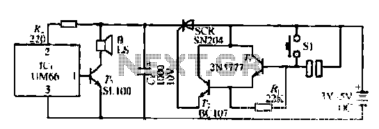
A few custom integrated circuits began to play music. When the song ends, no electricity flows through the thyristor, which then cuts off the light, causing the phototransistor to activate. The system is designed with a touchpad; each touch...

A battery-powered, pushbutton-triggered TTL/CMOS-compatible source of debounced 5V logic pulses is a simple but handy piece of test equipment to have in any tool kit. The circuit's battery-powered operation complicates what would otherwise be a trivial exercise in switch-bounce...
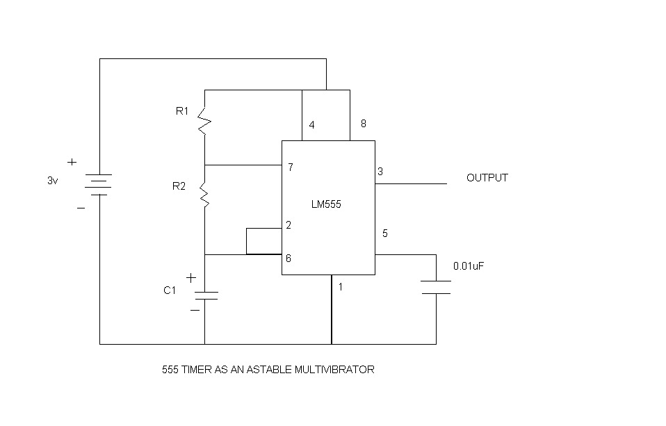
An astable multivibrator, commonly referred to as a free-running multivibrator, is a circuit that generates rectangular waves without the need for external triggering. The timing characteristics of this circuit are determined by the values of the resistors and capacitors...