


6 Digit Coded Ac Power Switch Circuit
#CD4013
#flip-flop
#optoisolator
#triac
#telephone keyboard
#6-digit code
#alarm
#AC power switch
#security
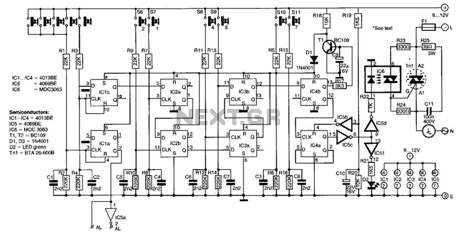
Description: This switch utilizes four CD4013BE dual flip-flops, an inverter, and an optoisolator to control a triac, allowing it to switch a 25-A AC load current. A standard 4x3 telephone keypad is employed for entering a 6-digit code. In the event of an incorrect code entry, a signal is generated to activate an alarm. Additionally, the system features a secret reset button that can be any number on the keypad for disarming purposes.
The described circuit leverages the capabilities of the CD4013BE dual flip-flops, which are D-type flip-flops known for their versatility in digital logic applications. In this configuration, the flip-flops store the entered 6-digit code, providing a means to compare it against a pre-defined code for validation. The inverter serves to ensure proper logic levels are maintained throughout the circuit, while the optoisolator provides electrical isolation between the low-voltage logic side and the high-voltage triac control side, enhancing safety and preventing potential damage from high voltage spikes.
The triac is responsible for switching the AC load, capable of handling up to 25 A, which is suitable for various applications including lighting, motor control, or other high-power devices. The use of a standard 4x3 telephone keypad simplifies user interaction, allowing easy entry of the 6-digit code.
In the event of an incorrect code entry, the circuit is designed to activate an alarm signal. This feature serves as a deterrent against unauthorized access and enhances the security of the system. The inclusion of a secret reset button adds an additional layer of flexibility, allowing users to disarm the system discreetly by entering a designated number on the keypad.
Overall, this circuit design effectively combines digital logic components with power control elements to create a robust and secure switching mechanism suitable for high-current AC applications. The thoughtful integration of user interface elements ensures usability while maintaining a high level of security. This switch uses four CD4013 BE dual flip-flops, an inverter, and an optoisolator to drive a triac. The circuit can switch 25-A ac load current. A standard 4x3 telephone keyboard is used to enter a 6-digit code. In case of a wrong code, a signal is available to activate ah alarm. The disarming method is a secret reset button that can be any number on the keyboard.
The described circuit leverages the capabilities of the CD4013BE dual flip-flops, which are D-type flip-flops known for their versatility in digital logic applications. In this configuration, the flip-flops store the entered 6-digit code, providing a means to compare it against a pre-defined code for validation. The inverter serves to ensure proper logic levels are maintained throughout the circuit, while the optoisolator provides electrical isolation between the low-voltage logic side and the high-voltage triac control side, enhancing safety and preventing potential damage from high voltage spikes.
The triac is responsible for switching the AC load, capable of handling up to 25 A, which is suitable for various applications including lighting, motor control, or other high-power devices. The use of a standard 4x3 telephone keypad simplifies user interaction, allowing easy entry of the 6-digit code.
In the event of an incorrect code entry, the circuit is designed to activate an alarm signal. This feature serves as a deterrent against unauthorized access and enhances the security of the system. The inclusion of a secret reset button adds an additional layer of flexibility, allowing users to disarm the system discreetly by entering a designated number on the keypad.
Overall, this circuit design effectively combines digital logic components with power control elements to create a robust and secure switching mechanism suitable for high-current AC applications. The thoughtful integration of user interface elements ensures usability while maintaining a high level of security. This switch uses four CD4013 BE dual flip-flops, an inverter, and an optoisolator to drive a triac. The circuit can switch 25-A ac load current. A standard 4x3 telephone keyboard is used to enter a 6-digit code. In case of a wrong code, a signal is available to activate ah alarm. The disarming method is a secret reset button that can be any number on the keyboard.
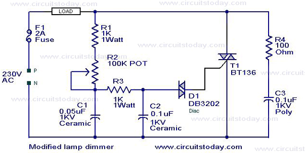
Light Dimmer Circuit TRIAC dimmer circuitCircuitWorking
This is a modification of the Simple Lamp Dimmer/Fan Regulator circuit that was previously posted. The operation of the circuit remains the same as the original; however, it now includes a snubber circuit composed of resistor R4 and capacitor C3...
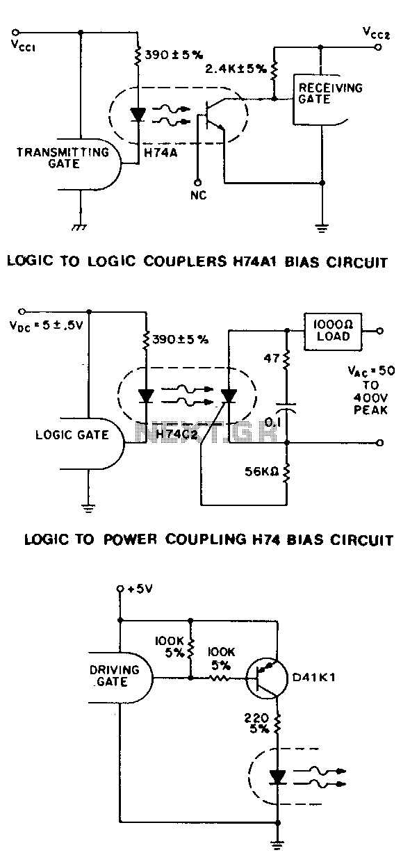
Optical-ttl-coupler
For higher speed applications, up to 1-MHz NRZ, the Schmitt-trigger output HllL series optoisolator provides many features. The 1.6-mA drive current allows fan-in circuitry to drive the IRED, while the 5-V, 270-0 sink capability and 100ns transition times of the...
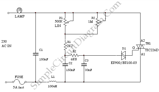
High Power AC Light Dimmer
This is a light dimmer circuit. It does not include any special features and is a typical TRIAC-based dimmer circuit. This circuit is designed to operate with...
A TRIAC-based light dimmer circuit is a common electronic design used to control the...
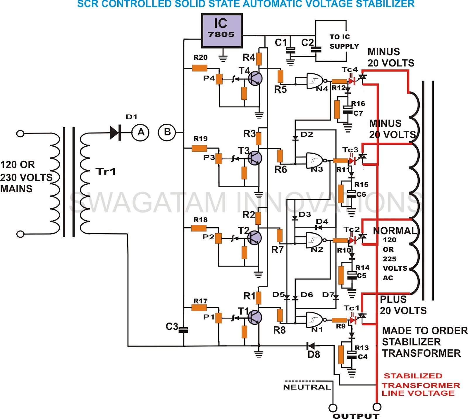
build solid state scrtriac controlled
This unique and hard-to-find triac-controlled AC voltage stabilizer circuit has been specifically designed for efficient voltage stabilization. With a solid-state design, the voltage switching transitions are smooth, resulting in minimal wear and tear. The proposed circuit provides four-step voltage stabilization...
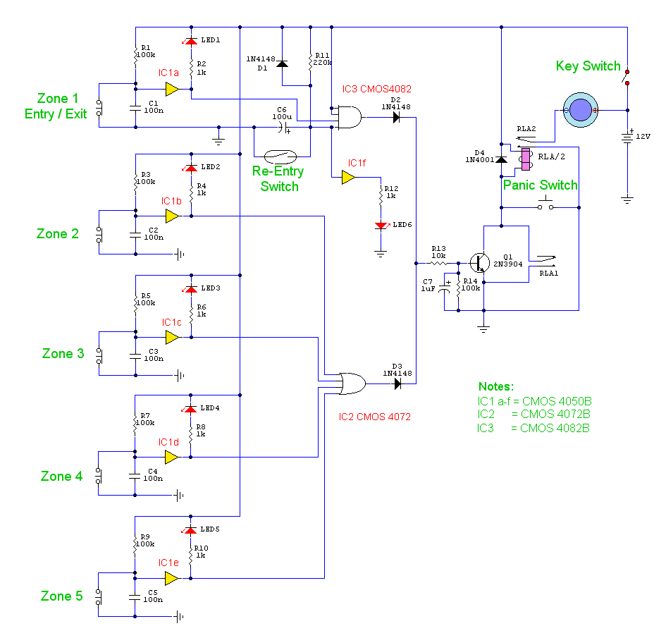
5 Zone Alarm Circuit
The objective is to enhance information transmission through the use of articles. Please contact us via email at [email protected] within 15 days if there are any issues related to article content, copyright, or other concerns. Prompt action will be taken...
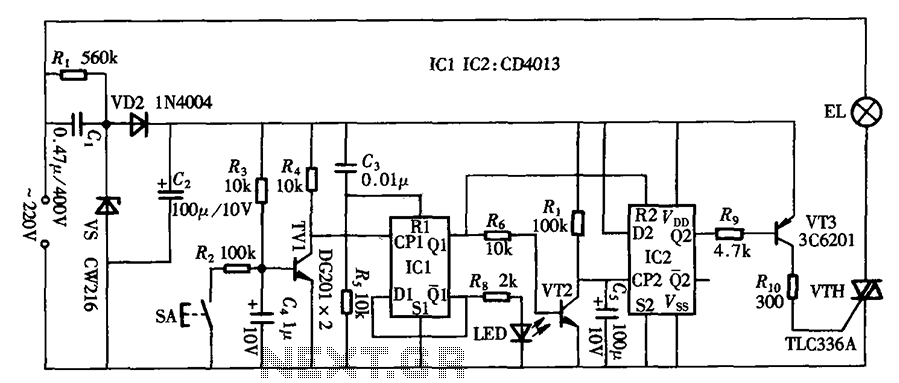
Touch delay switch circuit diagram CD4013 composed
The circuit primarily utilizes a touch-delay switch composed of a pair of D flip-flops (CD4013). It can be employed in power switch applications for various machines. The delay switch can also function as a lighting control and features a power...
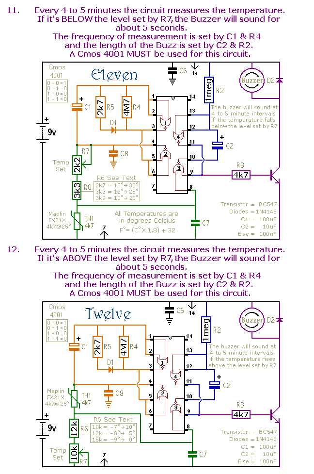
Mini Alarms
This is a selection of small self-contained alarm circuits. They have a very low standby current; and are suitable for battery operation.
The described alarm circuits are compact and designed for low power consumption, making them ideal for battery-powered applications. These...
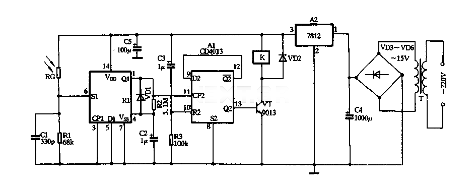
With a CD4013 produce laser light remote control switch
The circuit consists of a 220V AC input connected to a step-down transformer (T), followed by a bridge rectifier (VD3 to VD6) and a three-terminal voltage regulator (block A2) that provides a stable 12V DC output for digital integrated circuits....
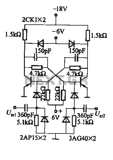
Practical flip-flop circuit
A flip-flop circuit with a memory function for pulse signals. It features two stable states: one where transistor VTi is off and VTZ is conducting, and another where VTi is conducting and VT2 is off. An external signal is sufficient...