


CB85-10 leakage protection circuit
#leakage protection
#trip coil
#test button
#simulated resistance
#safety circuit
#electrical safety
#protection device
#fault detection

Description: CB85-10 leakage protection circuit diagram, T for the trip coil, SB is the test button, Ri is simulated human resistance.
The CB85-10 leakage protection circuit is designed to enhance safety by detecting leakage currents and disconnecting the electrical supply to prevent electric shocks. The circuit includes a trip coil (T), which is the actuator responsible for opening the circuit when a leakage is detected. The test button (SB) allows users to simulate a fault condition to verify the functionality of the protection circuit. The simulated human resistance (Ri) represents the resistance of a human body, which is critical for determining the threshold at which the circuit will activate.
In this schematic, the trip coil is connected to a relay that interrupts the power supply when a leakage current exceeds a predetermined level. The test button is strategically placed in the circuit to facilitate routine testing, ensuring that the leakage protection system is operational. The simulated human resistance is typically set to approximate the resistance of a person under fault conditions, allowing the circuit to react appropriately to real-world scenarios.
The circuit operates under the principle of differential current sensing, where the current flowing through the live and neutral wires is continuously monitored. If a difference in current is detected, indicative of leakage, the trip coil is energized, causing the relay to open and disconnect the load. This design emphasizes reliability and safety, making it suitable for various applications in residential and commercial electrical systems. Regular testing via the test button is essential to maintain the integrity of the leakage protection mechanism. CB85-10 leakage protection circuit diagram, T for the trip coil, SB is the test button, Ri is simulated human resistance
The CB85-10 leakage protection circuit is designed to enhance safety by detecting leakage currents and disconnecting the electrical supply to prevent electric shocks. The circuit includes a trip coil (T), which is the actuator responsible for opening the circuit when a leakage is detected. The test button (SB) allows users to simulate a fault condition to verify the functionality of the protection circuit. The simulated human resistance (Ri) represents the resistance of a human body, which is critical for determining the threshold at which the circuit will activate.
In this schematic, the trip coil is connected to a relay that interrupts the power supply when a leakage current exceeds a predetermined level. The test button is strategically placed in the circuit to facilitate routine testing, ensuring that the leakage protection system is operational. The simulated human resistance is typically set to approximate the resistance of a person under fault conditions, allowing the circuit to react appropriately to real-world scenarios.
The circuit operates under the principle of differential current sensing, where the current flowing through the live and neutral wires is continuously monitored. If a difference in current is detected, indicative of leakage, the trip coil is energized, causing the relay to open and disconnect the load. This design emphasizes reliability and safety, making it suitable for various applications in residential and commercial electrical systems. Regular testing via the test button is essential to maintain the integrity of the leakage protection mechanism. CB85-10 leakage protection circuit diagram, T for the trip coil, SB is the test button, Ri is simulated human resistance
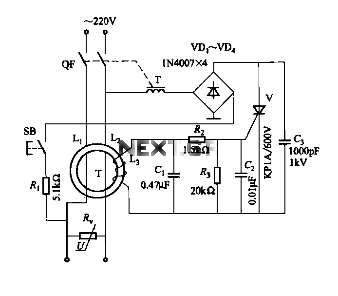
DBS-20-type leakage protection circuit
DBS-20 type leakage protection circuit
The DBS-20 type leakage protection circuit is designed to detect and prevent electrical leakage, thereby enhancing safety in electrical installations. This circuit operates by monitoring the current flowing through the live and neutral conductors. When an...

Safety Circuit Circuit
Due to the limited hold-on time of the delay circuits R1/C1 and R2/C2, both switches S1 and S2 must be activated simultaneously to energize the load.
The circuit in question involves a delay mechanism governed by the time constants associated with...
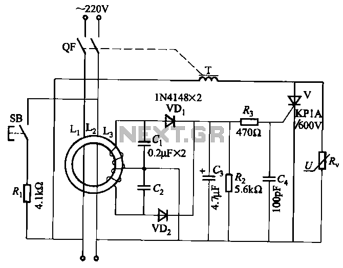
JBD3-10 leakage protection circuit
JBD3-10 leakage protection circuit
The JBD3-10 leakage protection circuit is designed to detect and mitigate leakage currents in electrical systems, enhancing safety and preventing potential hazards. This circuit employs a differential current transformer that continuously monitors the current flowing through the...
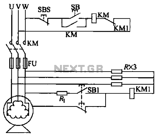
Resistive neutral leakage protection circuit
A voltage leakage protection circuit utilizing a resistive element as an auxiliary neutral point is illustrated in the accompanying figure. When selecting the resistance, it is essential to consider both the resistance value and power consistency.
The described voltage leakage protection...
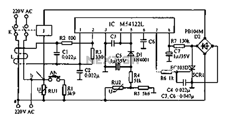
Leakage protection switch circuit diagram
The multifunction leakage protection switch utilizes the Nissan ASIC M54122L. It is designed to serve as a multi-function leakage protection switch. In the event of leakage or electric shock, the magnetic field generated through the inductor line and neutral cancels...