


Leakage protection switch circuit diagram
#leakage protection
#ASIC
#M54122L
#safety switch
#electric shock protection
#circuit protection
#home safety
#electrical safety
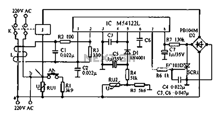
Description: The multifunction leakage protection switch utilizes the Nissan ASIC M54122L. It is designed to serve as a multi-function leakage protection switch. In the event of leakage or electric shock, the magnetic field generated through the inductor line and neutral cancels each other, preventing AC voltage from being produced across the coil. When leakage or electric shock occurs, the coil generates a voltage, causing pin 7 to produce a high signal that triggers a thyristor, resulting in the relay disconnecting the power supply. Overvoltage protection is provided through the components Ru1, Ru2, Ru4, Ru5, and D1. The Ru1 varistor absorbs overvoltage caused by lightning or neutral failure. When the supply voltage increases, the resistance of Ru decreases, leading to an increase in voltage across R5. When the supply voltage reaches approximately 275V, the voltage across R5 becomes about 1.8V, which triggers protection through R4 and D1.
The multifunction leakage protection switch featuring the Nissan ASIC M54122L is an advanced circuit designed to ensure electrical safety by detecting leakage currents and responding to electrical shocks. The core operation involves the interaction of magnetic fields generated by current flowing through inductor lines and neutral connections. In normal conditions, these magnetic fields counteract, resulting in no AC voltage across the coil. However, upon detection of a leakage current or electric shock, the coil generates a voltage, which is sensed by pin 7 of the ASIC. This condition activates a thyristor, which is a semiconductor device that acts as a switch, effectively disconnecting the relay from the power supply and thereby preventing potential hazards.
The overvoltage protection mechanism is critical in safeguarding the circuit from transient voltage spikes, such as those caused by lightning strikes or faults in the neutral line. The circuit employs a varistor (Ru1), which is designed to absorb excess voltage. As the supply voltage rises, the resistance of Ru1 decreases, allowing more current to flow. This results in an increase in voltage across resistor R5. When the voltage exceeds a threshold of approximately 275V, the voltage across R5 reaches about 1.8V, which is sufficient to trigger the protective action through the combination of resistors R4 and diode D1. This design ensures that the circuit remains operational under normal conditions while providing robust protection against electrical faults, thereby enhancing the safety and reliability of electrical systems where this multifunction leakage protection switch is implemented.As shown Multifunction leakage protection switch utilizing Nissan ASIC M54122L, it can be composed of multi-function leakage protection switch, when the leakage and electric sh ock, the magnetic field through the inductor line and neutral generated cancel each other on the coil AC voltage is not generated. When the leakage or electric shock, the coil generates a voltage, pin 7 produces a high triggered thyristor, so that the relay off the power.
Overvoltage protection by the Ru1, Ru2, Ru4, Ru5, D1 composition. Ru1 varistor for absorbing lightning or neutral failure caused by overvoltage. When the supply voltage is increased, Ru resistance becomes smaller, the R5 voltage increases when the supply voltage is equal to 275V, the voltage of about 1.8V on the R5 through R4, D1 trigger protection.
The multifunction leakage protection switch featuring the Nissan ASIC M54122L is an advanced circuit designed to ensure electrical safety by detecting leakage currents and responding to electrical shocks. The core operation involves the interaction of magnetic fields generated by current flowing through inductor lines and neutral connections. In normal conditions, these magnetic fields counteract, resulting in no AC voltage across the coil. However, upon detection of a leakage current or electric shock, the coil generates a voltage, which is sensed by pin 7 of the ASIC. This condition activates a thyristor, which is a semiconductor device that acts as a switch, effectively disconnecting the relay from the power supply and thereby preventing potential hazards.
The overvoltage protection mechanism is critical in safeguarding the circuit from transient voltage spikes, such as those caused by lightning strikes or faults in the neutral line. The circuit employs a varistor (Ru1), which is designed to absorb excess voltage. As the supply voltage rises, the resistance of Ru1 decreases, allowing more current to flow. This results in an increase in voltage across resistor R5. When the voltage exceeds a threshold of approximately 275V, the voltage across R5 reaches about 1.8V, which is sufficient to trigger the protective action through the combination of resistors R4 and diode D1. This design ensures that the circuit remains operational under normal conditions while providing robust protection against electrical faults, thereby enhancing the safety and reliability of electrical systems where this multifunction leakage protection switch is implemented.As shown Multifunction leakage protection switch utilizing Nissan ASIC M54122L, it can be composed of multi-function leakage protection switch, when the leakage and electric sh ock, the magnetic field through the inductor line and neutral generated cancel each other on the coil AC voltage is not generated. When the leakage or electric shock, the coil generates a voltage, pin 7 produces a high triggered thyristor, so that the relay off the power.
Overvoltage protection by the Ru1, Ru2, Ru4, Ru5, D1 composition. Ru1 varistor for absorbing lightning or neutral failure caused by overvoltage. When the supply voltage is increased, Ru resistance becomes smaller, the R5 voltage increases when the supply voltage is equal to 275V, the voltage of about 1.8V on the R5 through R4, D1 trigger protection.
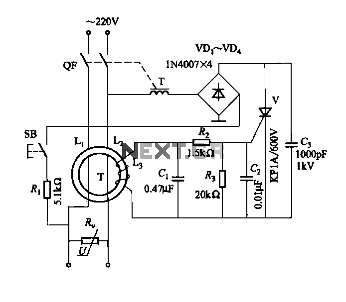
DBS-20-type leakage protection circuit
DBS-20 type leakage protection circuit
The DBS-20 type leakage protection circuit is designed to detect and prevent electrical leakage, thereby enhancing safety in electrical installations. This circuit operates by monitoring the current flowing through the live and neutral conductors. When an...

CB85-10 leakage protection circuit
CB85-10 leakage protection circuit diagram, T for the trip coil, SB is the test button, Ri is simulated human resistance.
The CB85-10 leakage protection circuit is designed to enhance safety by detecting leakage currents and disconnecting the electrical supply to prevent...

Electronic Safety Switch Circuit
SI and S2 must be pressed within 200 ms of each other to activate K1. The hold time is adjustable via K7. Additionally, the overlap time of SI and S2 can be modified by changing C1 and C2 or R1...
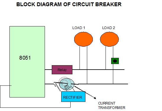
electronic circuit breaker
A circuit breaker is an automatically operated electrical switch designed to protect an electrical circuit from damage caused by overload or short circuit. Its basic function is to detect a fault condition and, by interrupting continuity, immediately discontinue electrical flow....
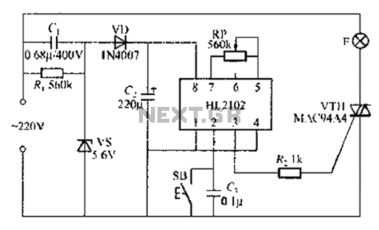
By ASIC delay lamp circuit
A thirty mining lamp control ASIC production delay lamp circuit is straightforward. It utilizes the HL2102 IC from Wuxi Love Core Microelectronics Co., Ltd. The circuit is designed to control a light with a timed delay, allowing for regular intervals...
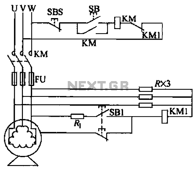
Resistive neutral leakage protection circuit
A voltage leakage protection circuit utilizing a resistive element as an auxiliary neutral point is illustrated in the accompanying figure. When selecting the resistance, it is essential to consider both the resistance value and power consistency.
The described voltage leakage protection...
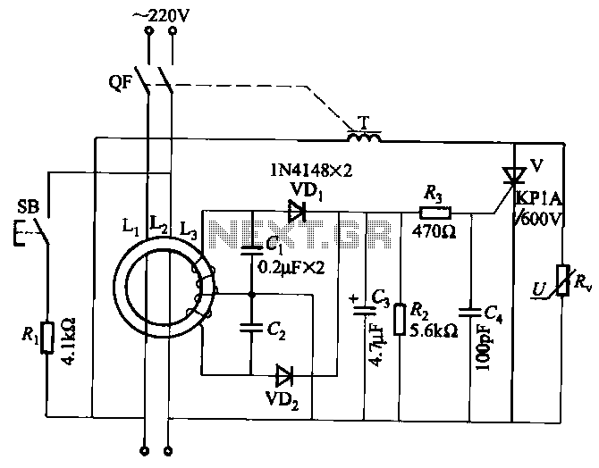
JBD3-10 leakage protection circuit
JBD3-10 leakage protection circuit
The JBD3-10 leakage protection circuit is designed to detect and mitigate leakage currents in electrical systems, enhancing safety and preventing potential hazards. This circuit employs a differential current transformer that continuously monitors the current flowing through the...