


Door Knob Touch Alarm
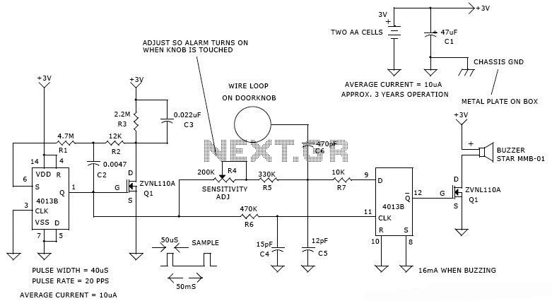
Description: This is a door knob touch alarm designed for home security purposes. The alarm is activated when someone touches the metal door knob. However, this circuit will not function on a fully metal door.
The door knob touch alarm circuit utilizes a capacitive sensing technique to detect the presence of a person's hand near the door knob. The core components of the circuit typically include a capacitive sensor, a microcontroller or comparator for signal processing, and an audible alarm or notification system.
When a person approaches the door and touches the metal knob, the capacitive sensor detects the change in capacitance caused by the human body. This change triggers the microcontroller, which processes the signal and activates the alarm system. The alarm can be configured to emit a sound through a buzzer or send a notification to a connected security system.
It is important to note that the effectiveness of this circuit is limited to non-metallic doors or doors with non-conductive surfaces, as the presence of a fully metal door would interfere with the capacitive sensing mechanism. To enhance the performance of the circuit, it may be beneficial to incorporate additional features such as adjustable sensitivity settings or a delay mechanism to prevent false alarms due to incidental contact.
The schematic for this circuit typically includes a power supply section, the capacitive sensor input, the signal processing unit, and the output stage connected to the alarm system. Proper layout and grounding techniques should be employed to minimize interference and ensure reliable operation.This is door knob touch alarm for your home security purpose. The alarm will be activated when someone touch the metal door knod. This circuit wont work on full metal door. Download the schematic drawing This is door knob touch alarm for your home security purpose. The alarm will be activated when someone touch the metal door knod. This ci rcuit won`t work on full metal door.
The door knob touch alarm circuit utilizes a capacitive sensing technique to detect the presence of a person's hand near the door knob. The core components of the circuit typically include a capacitive sensor, a microcontroller or comparator for signal processing, and an audible alarm or notification system.
When a person approaches the door and touches the metal knob, the capacitive sensor detects the change in capacitance caused by the human body. This change triggers the microcontroller, which processes the signal and activates the alarm system. The alarm can be configured to emit a sound through a buzzer or send a notification to a connected security system.
It is important to note that the effectiveness of this circuit is limited to non-metallic doors or doors with non-conductive surfaces, as the presence of a fully metal door would interfere with the capacitive sensing mechanism. To enhance the performance of the circuit, it may be beneficial to incorporate additional features such as adjustable sensitivity settings or a delay mechanism to prevent false alarms due to incidental contact.
The schematic for this circuit typically includes a power supply section, the capacitive sensor input, the signal processing unit, and the output stage connected to the alarm system. Proper layout and grounding techniques should be employed to minimize interference and ensure reliable operation.This is door knob touch alarm for your home security purpose. The alarm will be activated when someone touch the metal door knod. This circuit wont work on full metal door. Download the schematic drawing This is door knob touch alarm for your home security purpose. The alarm will be activated when someone touch the metal door knod. This ci rcuit won`t work on full metal door.
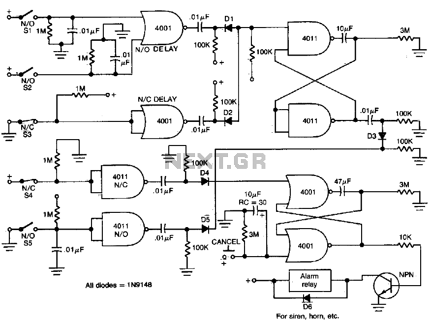
Home security monitor system
This circuit provides normally open (NO) and normally closed (NC) contacts SI, S2, and S3 to activate the alarm after a 30-second delay. S4 and S5 operate instantly. The CANCEL switch resets the alarm.
The described circuit functions as a delay...

Programmable Home Security Alarm System
A low-cost, high-performance programmable home security system utilizing a few LDRs as input sensors. When the sensors are triggered, the system can dial a user-specified phone number using a built-in DTMF generator and activate a high-power audio alarm and lights....
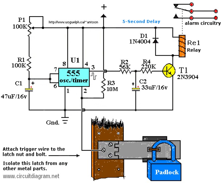
touch alarm system
The Touch Alarm circuit is commonly utilized for security purposes and is typically installed on doors. Its advantages include low cost and difficulty in detection by burglars or intruders. An example of a touch alarm circuit is designed by Tony...
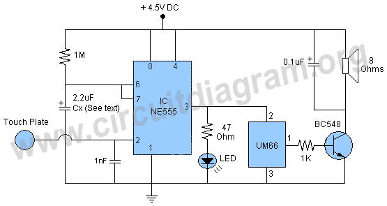
touch alarm with um66 ic
This project involves a 555 touch alarm circuit integrated with an UM66 melody IC. The circuit is designed to emit a melodious alarm sound for a predetermined duration when a person touches the metal plate or touch plate depicted in...
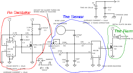
Doorknob touch alarm
The project was originally intended as a present for my brothers dorm room, but a bad capacitor and the lack of a proper oscilloscope caused delays. It has not made it off the breadboard, and it probably will not until...