


Infrared burglar alarm circuit schematic
#infrared
#NE555
#burglar alarm
#transmitter
#receiver
#40kHz
#sensor
#security system
#multivibrator
#IR beam
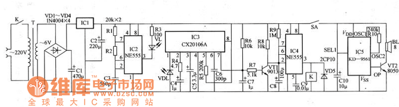
Description: The schematic for an infrared burglar alarm circuit is depicted in Figure 1. The infrared transmitter operates as a multivibrator with an oscillation frequency of 40 kHz, utilizing the NE555 integrated circuit (IC2), along with resistors R1 and R2 and capacitor C3. The VLS component serves as the infrared emission probe, capable of radiating a 40 kHz high-frequency signal externally to create the infrared beam. The VDL component acts as the infrared receiver probe.
The infrared burglar alarm circuit is designed to detect unauthorized entry by utilizing a pair of infrared probes: an emitter and a receiver. The NE555 timer IC is configured in astable mode to generate a continuous square wave signal at a frequency of 40 kHz. This frequency is chosen to optimize the detection range and reduce interference from ambient light sources.
Resistors R1 and R2, along with capacitor C3, are critical in determining the frequency of oscillation. The values of these components can be adjusted to modify the duty cycle and frequency of the output signal, allowing for customization based on specific application requirements. The VLS infrared emission probe emits modulated infrared light, creating an invisible barrier. When an intruder interrupts this beam, the VDL infrared receiver probe detects the absence of the signal.
The output from the infrared receiver can be interfaced with additional circuitry, such as a microcontroller or alarm system, to trigger an alert or notification upon beam interruption. This circuit can be powered by a DC power supply, ensuring that it remains operational under various conditions. The design can be further enhanced by incorporating additional features, such as adjustable sensitivity, multiple beam paths for increased security, and integration with wireless communication modules to send alerts to a remote monitoring system.Infrared burglar alarm circuit schematic is shown in Figure 1. Infrared transmitter is a multivibrator with oscillation frequency being 40kHz, and it is composed of IC2 ( NE555 ), R1, R2 and C3. VLS is the infrared emission probe which can be used to radiate 40kHz high-frequency externally to form the IR beam.
VDL is the infrared receiver probe, and it form..
The infrared burglar alarm circuit is designed to detect unauthorized entry by utilizing a pair of infrared probes: an emitter and a receiver. The NE555 timer IC is configured in astable mode to generate a continuous square wave signal at a frequency of 40 kHz. This frequency is chosen to optimize the detection range and reduce interference from ambient light sources.
Resistors R1 and R2, along with capacitor C3, are critical in determining the frequency of oscillation. The values of these components can be adjusted to modify the duty cycle and frequency of the output signal, allowing for customization based on specific application requirements. The VLS infrared emission probe emits modulated infrared light, creating an invisible barrier. When an intruder interrupts this beam, the VDL infrared receiver probe detects the absence of the signal.
The output from the infrared receiver can be interfaced with additional circuitry, such as a microcontroller or alarm system, to trigger an alert or notification upon beam interruption. This circuit can be powered by a DC power supply, ensuring that it remains operational under various conditions. The design can be further enhanced by incorporating additional features, such as adjustable sensitivity, multiple beam paths for increased security, and integration with wireless communication modules to send alerts to a remote monitoring system.Infrared burglar alarm circuit schematic is shown in Figure 1. Infrared transmitter is a multivibrator with oscillation frequency being 40kHz, and it is composed of IC2 ( NE555 ), R1, R2 and C3. VLS is the infrared emission probe which can be used to radiate 40kHz high-frequency externally to form the IR beam.
VDL is the infrared receiver probe, and it form..
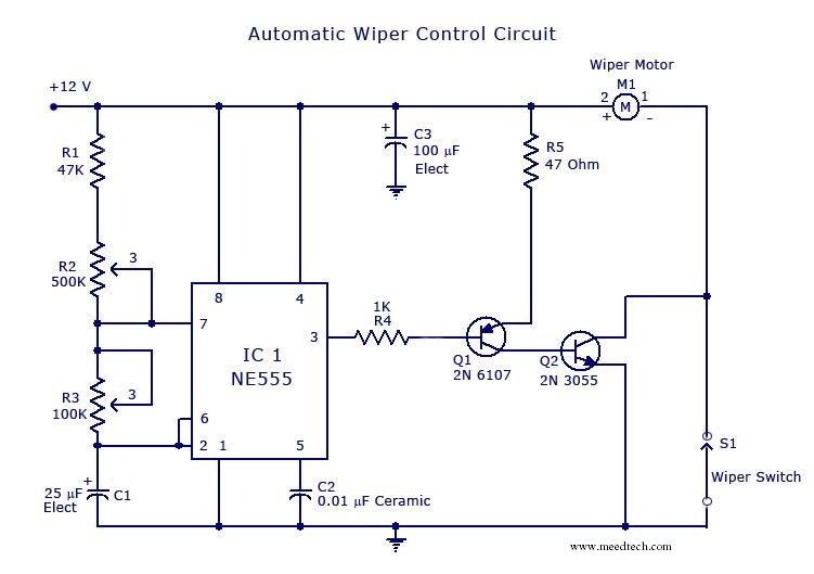
automatic wiper control
The circuit is built around an astable multivibrator using the NE555 timer. The output at pin 3 remains high for a duration determined by resistor R2 and low for a duration set by resistor R3. The low output pulse activates...
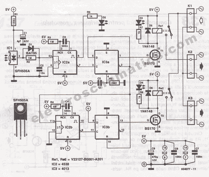
Remote Infrared Switch Circuit
The SFH505A, manufactured by Siemens, integrates an infrared diode receiver, amplifier, demodulator, and a band-pass filter to minimize interferences. This circuit operates effectively in various applications.
The SFH505A is a versatile optical receiver module designed for infrared communication systems. It is...
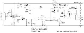
Infrared Toggle Switch schematic diagram
All modern infrared (IR) remote control devices generate a continuous coded stream of pulses at 37.9 kHz when any button on the device is pressed. These IR pulses are received and decoded by a compatible device, such as a television...
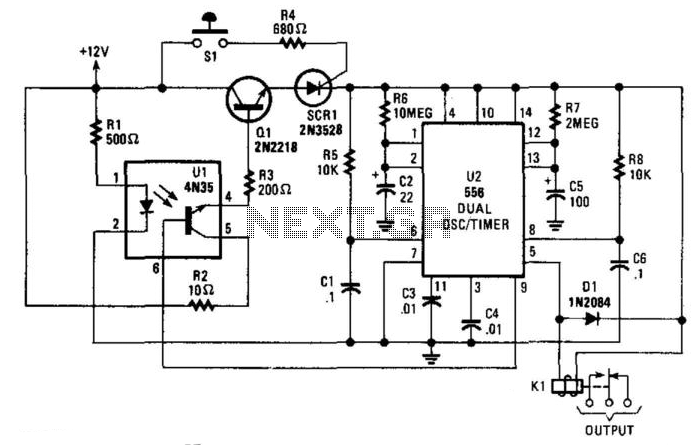
Burglar Alarm With Timed Shutoff
When the SI (sensor) is closed, power is applied to U2, a dual timer. After a time determined by C2, CI is energized after a predetermined time determined by the value of C5. Pin 9 of U2 becomes low, switching...
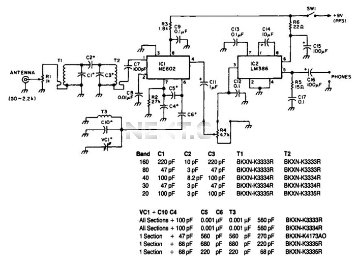
Conversion Receiver For 160 To 20M Circuit
Note that T1 and T2 are TOKO components, including part numbers for the coils T1 and T2. The direct-conversion receiver shown utilizes a double-tuned input network made from readily available TOKO coils. IC1, an NE602, serves as a voltage-controlled oscillator...
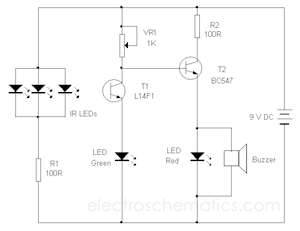
Infrared beam barrier proximity sensor
The circuit utilizes the widely used Sharp IR module (the Vishay module can also be employed). The pin numbers indicated in the circuit are applicable to both the Sharp and Vishay modules. For other modules, it is advisable to consult...
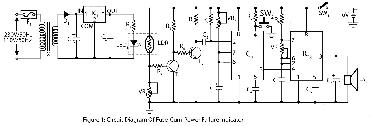
Fuse-Cum-Power Failure Indicator with alarm
The Fuse Cum Power Failure Indicator utilizes a thermistor and a timer IC (NE555) in its circuit design. The circuit diagram includes a parts list for the fuse cum power failure indicator, which signals instances of power failure.
The Fuse Cum...
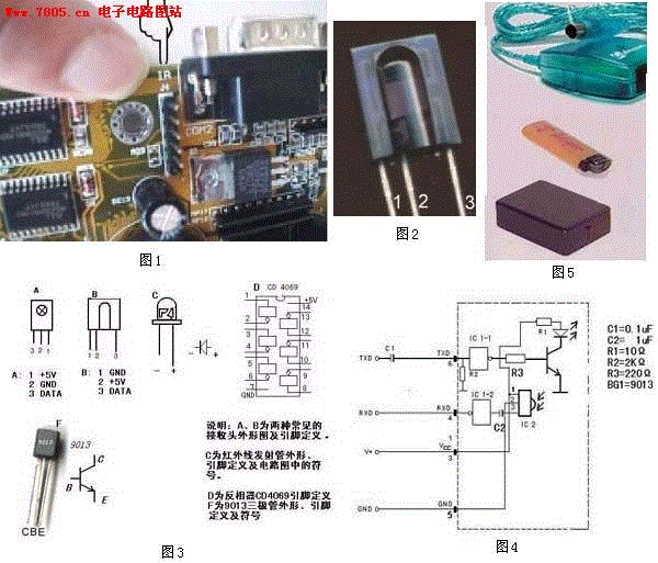
DIY computer infrared interface
A and B are two common contacts, along with an outline drawing and pin definitions. C refers to the shape of the infrared emission tube, including its pin definition and schematic symbol. CD4069 provides the pin definitions for the inverter...
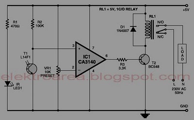
control relay with infrared circuit
Typically, home appliances are controlled using switches, sensors, and similar devices. However, physical interaction with switches can pose safety risks in the event of a short circuit. The circuit outlined here eliminates the need for physical contact to operate appliances....