


Simple fire alarm circuit using IC timer NE555
#NE555
#timer
#LDR
#light sensor
#smoke detection
#audio oscillator
#alarm circuit
#free running oscillator
#fire alarm
#sensor circuit
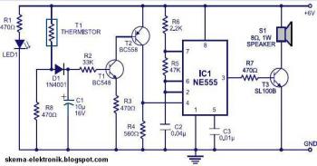
Description: This is a simple smoke alarm circuit using a timer IC, the NE555. The circuit operates by illuminating a Light Dependent Resistor (LDR) with a lamp. When smoke obscures the light from the lamp, the resistance of the LDR changes, triggering the alarm. The NE555 (IC1) is configured as a free-running oscillator operating at audio frequencies. Transistors T1 and T2 control the NE555. The output from pin 3 of IC1 is connected to the base of transistor T3 (SL100), which activates the speaker to produce an alarm sound. The frequency of the NE555 is determined by the resistors R5 and R6, as well as the capacitor C2. When the thermistor heats up, it creates a low-resistance path for positive voltage to reach the base of transistor T1 via diode D1 and resistor R2. Capacitor C1 charges to the positive supply voltage, extending the duration of the alarm. A larger value of C1 results in greater positive bias at the base of transistor T1 (BC548). The collector of T1 is connected to the base of transistor T2, which supplies a positive voltage to pin 4 (reset) of IC1 (NE555). Resistor R4 is chosen to keep the NE555 inactive when there is no positive voltage present. Diode D1 prevents the discharge of capacitor C1 when the thermistor is connected to the positive supply voltage, which cools down and provides a high resistance path, also blocking the forward biasing of transistor T1.
This smoke alarm circuit utilizes the NE555 timer IC in an astable configuration, producing a continuous square wave output that can be used to drive an audio alarm. The LDR acts as a light sensor, and its resistance decreases when exposed to light, allowing for a threshold detection of smoke that obscures this light. The interaction between the LDR and the thermistor is crucial for the operation; when smoke is detected, the change in resistance triggers the alarm system.
The design incorporates transistors for signal amplification and switching. Transistor T1 (BC548) is responsible for amplifying the signal from the thermistor, while T2 serves to reset the NE555 timer, ensuring that the alarm remains inactive in normal conditions. The output from the NE555 is used to drive T3 (SL100), which in turn activates the speaker to emit an alarm sound, alerting users to the presence of smoke.
The choice of resistors R5 and R6, along with the capacitor C2, determines the frequency of the oscillation produced by the NE555, which is typically set within the audio range to ensure the alarm is audible. The capacitor C1 plays a critical role in timing; it determines how long the alarm will sound once triggered. The use of diode D1 is essential for maintaining the charge in C1, preventing it from discharging prematurely and ensuring that the alarm remains activated until the smoke condition is resolved.
Overall, this circuit is a practical application of the NE555 timer and demonstrates the integration of various electronic components to create a functional smoke detection and alarm system. Proper selection of component values and careful design considerations ensure reliable operation in detecting smoke and providing timely alerts.Here the simple file alarm circuit based timer ID NE555. The works is simple, the lamp give light to the LDR (Light Depending Resistor) as light sensor. When the light from the lamp covered with smoke then the LDR will change its resistance value and then activated the alarm. The IC1 (NE555) is configured as a free running oscillator at audio freq uency. The transistors T1 and T2 drive IC1. The output(pin 3) of IC1 is couples to base of transistor T3(SL100), which drives the speaker to generate alarm sound. The frequency of NE555 depends on the values of resistances R5 and R6 and capacitance C2. When thermistor becomes hot, it gives a low-resistance path for the positive voltage to the base of transistor T1 through diode D1 and resistance R2.
Capacitor C1 charges up to the positive supply voltage and increases the the time for which the alarm is ON. The larger the value of C1, the larger the positive bias applied to the base of transistor T1 (BC548).
As the collector of T1 is coupled to the base of transistor T2, the transistor T2 provides a positive voltage to pin 4 (reset) of IC1 (NE555). Resistor R4 is selected s0 that NE555 keeps inactive in the absence of the positive voltage. Diode D1 stops discharging of capacitor C1 when the thermistor is in connection with the positive supply voltage cools out and provides a high resistance path.
It also inhibits the forward biasing of transistor T1.
This smoke alarm circuit utilizes the NE555 timer IC in an astable configuration, producing a continuous square wave output that can be used to drive an audio alarm. The LDR acts as a light sensor, and its resistance decreases when exposed to light, allowing for a threshold detection of smoke that obscures this light. The interaction between the LDR and the thermistor is crucial for the operation; when smoke is detected, the change in resistance triggers the alarm system.
The design incorporates transistors for signal amplification and switching. Transistor T1 (BC548) is responsible for amplifying the signal from the thermistor, while T2 serves to reset the NE555 timer, ensuring that the alarm remains inactive in normal conditions. The output from the NE555 is used to drive T3 (SL100), which in turn activates the speaker to emit an alarm sound, alerting users to the presence of smoke.
The choice of resistors R5 and R6, along with the capacitor C2, determines the frequency of the oscillation produced by the NE555, which is typically set within the audio range to ensure the alarm is audible. The capacitor C1 plays a critical role in timing; it determines how long the alarm will sound once triggered. The use of diode D1 is essential for maintaining the charge in C1, preventing it from discharging prematurely and ensuring that the alarm remains activated until the smoke condition is resolved.
Overall, this circuit is a practical application of the NE555 timer and demonstrates the integration of various electronic components to create a functional smoke detection and alarm system. Proper selection of component values and careful design considerations ensure reliable operation in detecting smoke and providing timely alerts.Here the simple file alarm circuit based timer ID NE555. The works is simple, the lamp give light to the LDR (Light Depending Resistor) as light sensor. When the light from the lamp covered with smoke then the LDR will change its resistance value and then activated the alarm. The IC1 (NE555) is configured as a free running oscillator at audio freq uency. The transistors T1 and T2 drive IC1. The output(pin 3) of IC1 is couples to base of transistor T3(SL100), which drives the speaker to generate alarm sound. The frequency of NE555 depends on the values of resistances R5 and R6 and capacitance C2. When thermistor becomes hot, it gives a low-resistance path for the positive voltage to the base of transistor T1 through diode D1 and resistance R2.
Capacitor C1 charges up to the positive supply voltage and increases the the time for which the alarm is ON. The larger the value of C1, the larger the positive bias applied to the base of transistor T1 (BC548).
As the collector of T1 is coupled to the base of transistor T2, the transistor T2 provides a positive voltage to pin 4 (reset) of IC1 (NE555). Resistor R4 is selected s0 that NE555 keeps inactive in the absence of the positive voltage. Diode D1 stops discharging of capacitor C1 when the thermistor is in connection with the positive supply voltage cools out and provides a high resistance path.
It also inhibits the forward biasing of transistor T1.

Simple Car theft alarm system circuit using NE555
The utility vehicle anti-theft alarm circuit consists primarily of two main components essential for its operation. The security circuit is activated when the vehicle owner departs from the vehicle, utilizing an anti-theft switch (S B) to engage the alarm system.
The...
Sun wake-up call
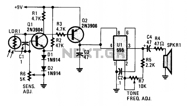
A cadmium sulfide photocell (LDR1), which functions as a light-dependent resistor, is connected to the base and collector of an NPN transistor (Q1). When light strikes LDR1, its internal resistance decreases from a very high value (in darkness) to a...
Timing within the one-chip computer Counter and interrupt system
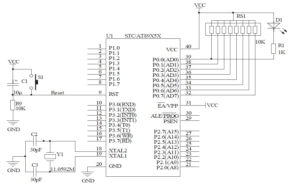
This document will present an overview of two critical components within a one-chip computer: the timing/counter system and the interrupt system. Through this explanation, readers will gain insight into the operating principles of these systems. For illustration, consider an alarm...
Radio Collar Transmitter Circuit
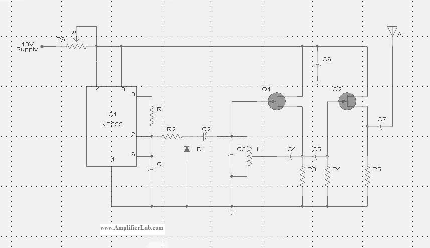
The circuit diagram of the Radio Collar Transmitter is presented here. This circuit is based on the NE555 integrated circuit, which serves as the central component.
The Radio Collar Transmitter circuit utilizes the NE555 timer IC to generate a modulated signal...
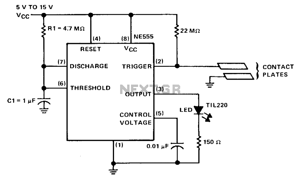
Touch switch
The circuit consists of a NE555 monostable timer, with a unique triggering method. The trigger input is held at a high voltage level by a 22-ohm resistor. When the contact plates are engaged, the operator's skin resistance decreases the total...
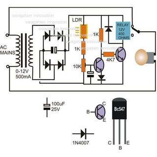
Light Activated Day Night Switch Circuit
This circuit diagram illustrates a light-activated switch utilizing the National Semiconductor comparator IC LM311 and a light-dependent resistor (LDR). The configuration is based on a voltage comparator circuit centered around IC1. The non-inverting input of IC1 receives a reference voltage...
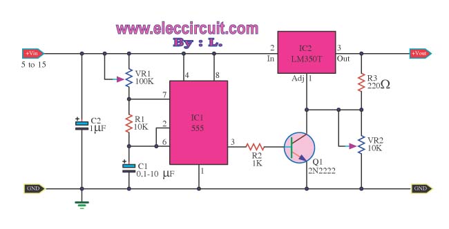
Pulse Generator by IC LM350T and 555
This is a Power Pulse Generator Circuit that utilizes the integrated circuit NE555 as a square wave oscillator generator. The frequency can be adjusted by varying resistor R1. The output from the NE555 is then sent to a transistor (2N2222)...
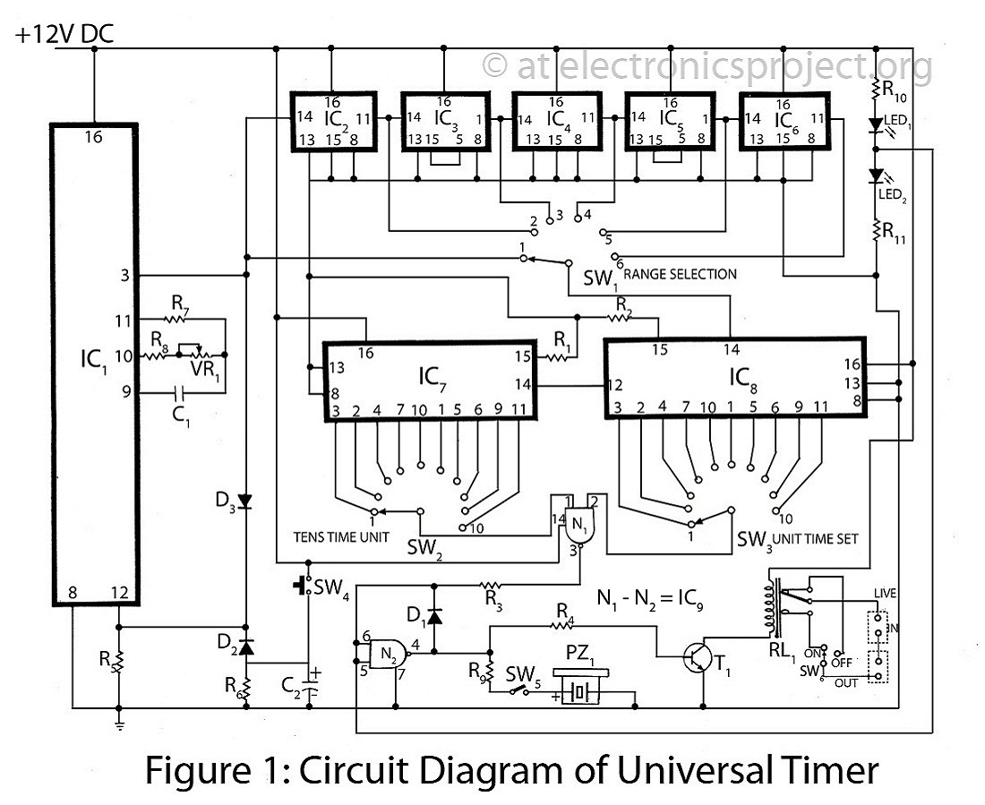
The Universal Timer with description
The Universal Timer is a highly versatile timer project that accommodates a wide range of time periods, from 1/10th of a second to 100 hours. This circuit diagram includes a comprehensive description of various timer circuits associated with the universal...
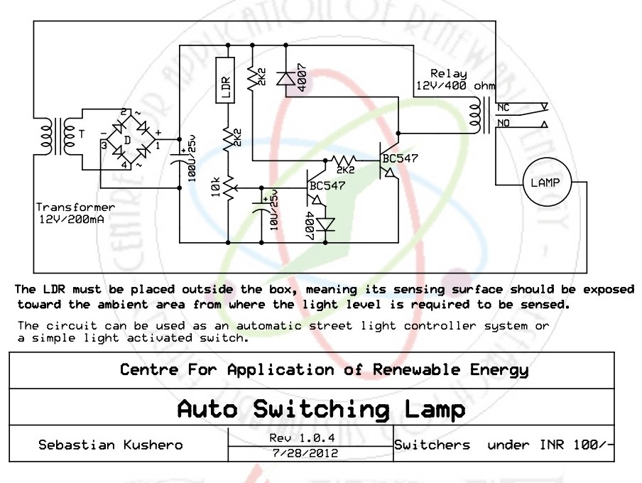
Light Activated Switch
The light-activated switch circuit can be used for switching off a particular lamp or group of lamps in response to varying ambient light levels.
The light-activated switch circuit utilizes a light-dependent resistor (LDR) as the primary sensing element to detect ambient...