


Timed Burglar Alarm N/O - N/C
#555 timer
#alarm circuit
#normally open
#normally closed
#self-resetting
#security
#timed alarm
#trigger
#burglar alarm
#home automation
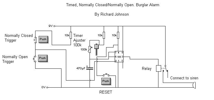
Description: This is a simple but effective alarm circuit that can reset itself after a user-defined time. It features normally open and normally closed triggers, enhancing its practicality. The circuit utilizes a 555 timer, allowing the alarm to automatically reset after a predetermined duration, which is adjustable using a variable resistor. The alarm includes a reset switch that can be replaced with a key switch for added security, and the triggers can be modified to accommodate various types of door or window switches. The circuit employs a relay connected to a siren, but the siren can be substituted with other devices. The circuit operates on a voltage range of 4V to 16V, with a nominal supply of 9V.
The alarm circuit is designed around the versatile 555 timer IC, which is configured in monostable mode. In this configuration, the timer generates a single output pulse when triggered. The duration of this pulse, which determines how long the alarm remains active, is set by the values of the resistor and capacitor connected to the timer. The variable resistor allows for easy adjustment of the timing, providing flexibility for different applications.
The circuit includes both normally open (NO) and normally closed (NC) trigger inputs. This dual triggering capability allows the circuit to be integrated with various sensors, such as door or window switches, enhancing its usability in security applications. When the circuit is triggered, the 555 timer activates the relay, which in turn powers the siren or any other connected alarm device.
The reset switch is a critical feature that allows the user to deactivate the alarm manually. For enhanced security, this switch can be replaced with a key switch, preventing unauthorized access to the reset function. The relay used in the circuit is capable of handling the current required by the siren, ensuring reliable operation.
Powering the circuit with a supply voltage of 9V is optimal, but it can function within a range of 4V to 16V, making it adaptable for different power sources. This flexibility in voltage supply allows the circuit to be used in various environments and applications.
The overall design of this alarm circuit emphasizes simplicity and effectiveness, making it suitable for personal security systems. The adjustable timing, dual trigger options, and customizable output make it a practical solution for enhancing security in residential or commercial settings.This is a simple but effective alarm circuit which can reset its self after a time that you select. it has normally open and normally closed triggers which make this circuit very practical. This alarm has normally open and normally closed triggers. It`s on a 555 timer so the alarm will reset it`s self after a certain amount of time. The time is ad justable with the variable resistor in the circuit. The alarm has a reset switch which you can replace with a key switch to make it more secure, and you can change the triggers to other types of door or window switched too. The alarmuses a relay which is connected to a siren but you can replace the siren with whatever you want.
The circuit is running off 9VOLTS but can range from 4V - 16V. Disclaimer: All the information present on this site are for personal use only. No commercial use is permitted without the prior permission from authors of this website. All content on this site is provided as is and without any guarantee on any kind, implied or otherwise. We cannot be held responsible for any errors, omissions, or damages arising out of use of information available on this web site.
The content in this site may contain COPYRIGHTED information and should not be reproduced in any way without prior permission from the authors.
The alarm circuit is designed around the versatile 555 timer IC, which is configured in monostable mode. In this configuration, the timer generates a single output pulse when triggered. The duration of this pulse, which determines how long the alarm remains active, is set by the values of the resistor and capacitor connected to the timer. The variable resistor allows for easy adjustment of the timing, providing flexibility for different applications.
The circuit includes both normally open (NO) and normally closed (NC) trigger inputs. This dual triggering capability allows the circuit to be integrated with various sensors, such as door or window switches, enhancing its usability in security applications. When the circuit is triggered, the 555 timer activates the relay, which in turn powers the siren or any other connected alarm device.
The reset switch is a critical feature that allows the user to deactivate the alarm manually. For enhanced security, this switch can be replaced with a key switch, preventing unauthorized access to the reset function. The relay used in the circuit is capable of handling the current required by the siren, ensuring reliable operation.
Powering the circuit with a supply voltage of 9V is optimal, but it can function within a range of 4V to 16V, making it adaptable for different power sources. This flexibility in voltage supply allows the circuit to be used in various environments and applications.
The overall design of this alarm circuit emphasizes simplicity and effectiveness, making it suitable for personal security systems. The adjustable timing, dual trigger options, and customizable output make it a practical solution for enhancing security in residential or commercial settings.This is a simple but effective alarm circuit which can reset its self after a time that you select. it has normally open and normally closed triggers which make this circuit very practical. This alarm has normally open and normally closed triggers. It`s on a 555 timer so the alarm will reset it`s self after a certain amount of time. The time is ad justable with the variable resistor in the circuit. The alarm has a reset switch which you can replace with a key switch to make it more secure, and you can change the triggers to other types of door or window switched too. The alarmuses a relay which is connected to a siren but you can replace the siren with whatever you want.
The circuit is running off 9VOLTS but can range from 4V - 16V. Disclaimer: All the information present on this site are for personal use only. No commercial use is permitted without the prior permission from authors of this website. All content on this site is provided as is and without any guarantee on any kind, implied or otherwise. We cannot be held responsible for any errors, omissions, or damages arising out of use of information available on this web site.
The content in this site may contain COPYRIGHTED information and should not be reproduced in any way without prior permission from the authors.
555 boost converter
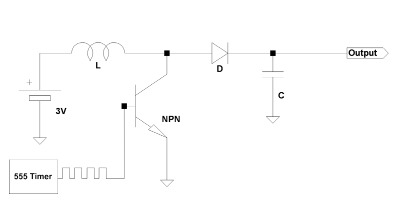
Boost circuits are an effective method for powering microcontrollers. Rather than using multiple AA batteries or a 9V battery (which is typically regulated down to 5V or 3.3V), one can boost the voltage from one or two AA batteries to...

electronics traffic light circuit
The clock pulses from the 555 astable circuit are sent into the 4017 decade counter. Each output becomes high in turn as the clock pulses are received. Appropriate outputs are combined with diodes to supply the amber and green LEDs.
The...
LED Flasher Using 555 IC
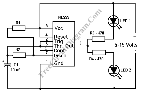
This LED flasher circuit is similar to the previous transistor-based LED flasher but utilizes a 555 integrated circuit as the primary component. The schematic diagram illustrates an LED flasher circuit that produces alternating LED flashing, with distinct flashing periods for...
Audio Astable Multivibrator Using IC 555 Circuit
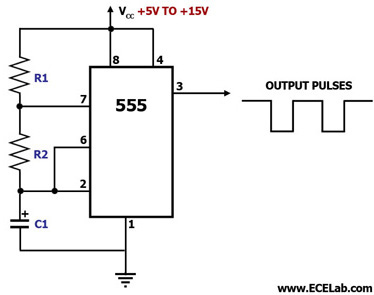
This circuit diagram illustrates the configuration of a 555 timer integrated circuit (IC) as an astable multivibrator. An astable multivibrator is a timing circuit characterized by unstable 'low' and 'high' states. Consequently, the output of an astable multivibrator continuously toggles...
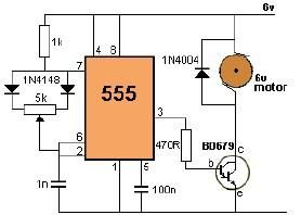
DC motor control using 555 timer circuit
This project utilizes a 555 timer to control the speed of a 6-volt DC motor. Speed adjustment is achieved by rotating a 50 kΩ potentiometer either to the left or right.
The circuit employs the 555 timer in astable mode, which...
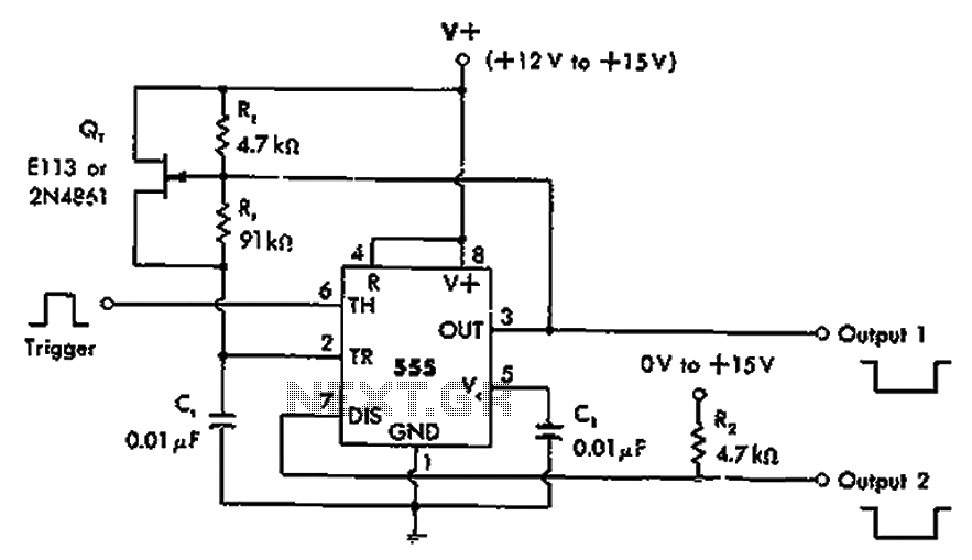
Inverting monostable circuit diagram
The timer 555 is activated by a positive trigger pulse, which results in negative output pulses. In scenarios where the duty cycle exceeds 99%, heavy loads can be disconnected from pin 7 without impacting timing accuracy, although loads exceeding pin...
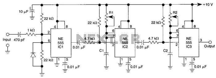
Delayed Pulse Generator Circuit
Three 555 IC timers are utilized in this circuit to create a simple delayed-pulse generator. IC1 functions as a waveform shaper to generate a rectangular waveform. IC2 generates a delaying pulse that triggers IC3 on the trailing edge of the...
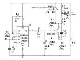
Jammer Circuit Using 555 Timer
The team is highly interested in the design of a jammer circuit and has begun working on it. However, they are experiencing issues with the circuit, specifically that the signal is not being jammed effectively.
The design of a jammer circuit...
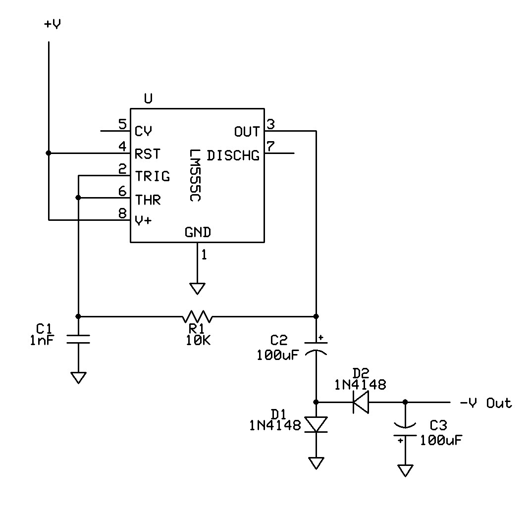
555 circuit Can supply enough neg voltage
Can a 555 negative supply circuit, like the one below I pulled from another schematic, supply enough negative voltage to an LM324 and an AD736JN?
The 555 timer integrated circuit can be configured to generate a negative voltage supply, which...