


Frequencies and Filters
#signal bandwidth
#frequency response
#sinewave
#attenuation
#high frequency
#amplifier limitations
#electronic filters
#audio engineering
#circuit design
#frequency range
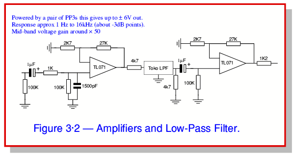
Description: One of the limitations affecting all real amplifiers is the finite signal bandwidth. This implies that any amplifier constructed or utilized has an upper limit to the range of sinewave frequencies it can amplify. Consequently, high-frequency signals may not be boosted and could instead be attenuated. Additionally, high-frequency signals may become distorted, altering their wave shape. Some amplifiers also have low-frequency limitations and cannot amplify frequencies below a certain threshold. It is essential to assess these effects to determine if a specific amplifier is suitable for a particular application. Furthermore, there are situations where it is necessary to intentionally modify the signal frequencies that a system will pass or amplify, necessitating deliberate filtering. Common examples include tone controls or equalization (EQ) controls, which are employed to adjust the overall tonal balance of sound signals or to correct for unwanted frequency-dependent effects. The effect of a filter is typically described in terms of frequency response, which defines the filter's behavior regarding its gain as a function of frequency. A typical example is illustrated in Figure 3.1, showing the measured power gain (or loss) as a function of frequency for a specific low-pass filter. This example is based on a commercial audio filter sold under the Toko brand name for use in hi-fi equipment. This filter is passive, meaning it contains no gain devices, only passive components such as resistors, capacitors, or inductors. Consequently, any unwanted losses in the filter must be counteracted. The overall circuit measured in this case is depicted in Figure 3.2, where the filter is positioned between two amplifiers that elevate the signal level. In this example, the filter's role is to prevent high frequencies from reaching the output, which is to be sampled by an ADC. The overall voltage gain is approximately G = 50 at 1 kHz. The Toko filter allows signals from direct current (DC) up to around 18 kHz to pass while attenuating higher frequencies. Although the frequency response displayed in Figure 3.1 is a common method for illustrating a filter's behavior, it does not capture the entire picture. As sinewave components traverse the filter, they may experience a delay that varies with frequency. This phenomenon is often represented through a plot of phase delay as a function of signal frequency. For the same filter, the measured phase delay as a function of frequency is illustrated in Figure 3.3. In this figure, the phase appears to fluctuate in a complex manner; however, the underlying behavior is simpler than it seems, attributable to two primary reasons.
The finite signal bandwidth of amplifiers is a crucial consideration in electronic circuit design. Understanding the limitations of frequency response allows engineers to select appropriate amplifiers for specific applications, ensuring optimal performance. The Toko low-pass filter serves as a practical example of how passive components can be employed to manage frequency response effectively. In audio applications, this filter is integrated between amplifiers to prevent high-frequency noise from interfering with the signal intended for analog-to-digital conversion (ADC).
The frequency response curve provides insight into how the filter affects signal gain across a spectrum of frequencies, while the phase delay information reveals how different frequency components are shifted in time as they pass through the filter. This delay can impact the overall performance of audio systems, particularly in applications where phase coherence is critical.
To analyze the performance of such filters, it is essential to consider both the magnitude response and the phase response. Engineers often utilize simulation tools and measurement equipment to evaluate these characteristics, ensuring that the design meets the intended specifications. The interplay between gain and phase response informs decisions regarding the integration of additional signal processing elements, such as equalizers or dynamic range compressors, to achieve the desired audio quality.
In summary, a thorough understanding of amplifier bandwidth limitations, filter design, and frequency response is vital for engineers working in audio and signal processing fields. By carefully considering these factors, it is possible to create systems that deliver high-quality, distortion-free audio signals while maintaining the integrity of the original sound.One of the limitations which affect all real amplifiers is that they all have a finite Signal Bandwidth. This means that whatever amplifier we build or use, we find that there is always an upper limit to the range of sinewave frequencies it can amplify.
This usually means that high frequencies signals won`t be boosted, and may attenuated instead. It also often means that high frequency signals may be Distorted i. e. their waveshape may be changed. Some amplifiers also have a low-frequency limitation as well, and are unable to amplify frequencies below some lower limit. We therefore need to be aware of, and be able to assess, these effects to decide if a specific amplifier is suitable for a given task.
In addition to the above, there are many situations where we deliberately want to alter the signal frequencies a system will pass on or amplify. There are many situations where deliberate filtering is needed. Some common examples are: Tone Controls` or EQ` (Equalisation) controls. These tend to be used to alter the overall tonal balance of sound signals, or correct for other unwanted frequency-dependent effects.
The most common and most obvious way to describe the effect of a filter is in terms of is Frequency Response. This defines the filter`s behaviour in terms of its Gain as a function of frequency. figure 3 ·1 shows a typical example. In this case Figure 3 ·1 shows the measured power gain (or loss!) as a function of frequency for a specific low-pass filter.
This example is based upon a commercial audio filter sold under the Toko` brand name for use in hi-fi equipment. This filter is Passive i. e. includes no gain devices, just passive components like resistors, capacitors, or inductors. As a result we need to counteract any unwanted losses in the filter. The overall circuit measured in this case is shown in figure 3 ·2. Here the filter actually sits in between two amplifiers which raise the signal level. The filter`s job in the system this example is taken from is to stop high frequencies from reaching the output which is to be sampled by an ADC.
The overall voltage gain is around G—50 at 1 kHz. The Toko filter passes signals from d. c. up to around 18 kHz but attenuates higher frequencies. Note also the pair of Although a frequency response of the kind shown in figure 3 ·1 is the most common way to display the behaviour of a filter, it doesn`t tell the whole story. When sinewave components pass through the filter they may also be delayed by an amount that depends upon their frequency.
This effect is often represented in terms of a plot of the Phase Delay as a function of signal frequency. For the same filter as before the measured Phase Delay as a function of frequency is shown in figure 3 ·3.
In figure 3 ·3 the phase seems to jump around` in quite a complex way. However the underlying behaviour is simpler than it appears. There are two reasons for this.
The finite signal bandwidth of amplifiers is a crucial consideration in electronic circuit design. Understanding the limitations of frequency response allows engineers to select appropriate amplifiers for specific applications, ensuring optimal performance. The Toko low-pass filter serves as a practical example of how passive components can be employed to manage frequency response effectively. In audio applications, this filter is integrated between amplifiers to prevent high-frequency noise from interfering with the signal intended for analog-to-digital conversion (ADC).
The frequency response curve provides insight into how the filter affects signal gain across a spectrum of frequencies, while the phase delay information reveals how different frequency components are shifted in time as they pass through the filter. This delay can impact the overall performance of audio systems, particularly in applications where phase coherence is critical.
To analyze the performance of such filters, it is essential to consider both the magnitude response and the phase response. Engineers often utilize simulation tools and measurement equipment to evaluate these characteristics, ensuring that the design meets the intended specifications. The interplay between gain and phase response informs decisions regarding the integration of additional signal processing elements, such as equalizers or dynamic range compressors, to achieve the desired audio quality.
In summary, a thorough understanding of amplifier bandwidth limitations, filter design, and frequency response is vital for engineers working in audio and signal processing fields. By carefully considering these factors, it is possible to create systems that deliver high-quality, distortion-free audio signals while maintaining the integrity of the original sound.One of the limitations which affect all real amplifiers is that they all have a finite Signal Bandwidth. This means that whatever amplifier we build or use, we find that there is always an upper limit to the range of sinewave frequencies it can amplify.
This usually means that high frequencies signals won`t be boosted, and may attenuated instead. It also often means that high frequency signals may be Distorted i. e. their waveshape may be changed. Some amplifiers also have a low-frequency limitation as well, and are unable to amplify frequencies below some lower limit. We therefore need to be aware of, and be able to assess, these effects to decide if a specific amplifier is suitable for a given task.
In addition to the above, there are many situations where we deliberately want to alter the signal frequencies a system will pass on or amplify. There are many situations where deliberate filtering is needed. Some common examples are: Tone Controls` or EQ` (Equalisation) controls. These tend to be used to alter the overall tonal balance of sound signals, or correct for other unwanted frequency-dependent effects.
The most common and most obvious way to describe the effect of a filter is in terms of is Frequency Response. This defines the filter`s behaviour in terms of its Gain as a function of frequency. figure 3 ·1 shows a typical example. In this case Figure 3 ·1 shows the measured power gain (or loss!) as a function of frequency for a specific low-pass filter.
This example is based upon a commercial audio filter sold under the Toko` brand name for use in hi-fi equipment. This filter is Passive i. e. includes no gain devices, just passive components like resistors, capacitors, or inductors. As a result we need to counteract any unwanted losses in the filter. The overall circuit measured in this case is shown in figure 3 ·2. Here the filter actually sits in between two amplifiers which raise the signal level. The filter`s job in the system this example is taken from is to stop high frequencies from reaching the output which is to be sampled by an ADC.
The overall voltage gain is around G—50 at 1 kHz. The Toko filter passes signals from d. c. up to around 18 kHz but attenuates higher frequencies. Note also the pair of Although a frequency response of the kind shown in figure 3 ·1 is the most common way to display the behaviour of a filter, it doesn`t tell the whole story. When sinewave components pass through the filter they may also be delayed by an amount that depends upon their frequency.
This effect is often represented in terms of a plot of the Phase Delay as a function of signal frequency. For the same filter as before the measured Phase Delay as a function of frequency is shown in figure 3 ·3.
In figure 3 ·3 the phase seems to jump around` in quite a complex way. However the underlying behaviour is simpler than it appears. There are two reasons for this.
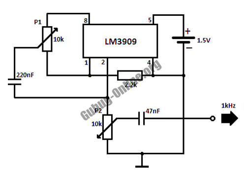
High Frequency Generator Circuit
This circuit design for a high-frequency waveform generator is highly beneficial for electronic experiments and designs. The circuit generates sine wave oscillations, but it can also be modified to produce triangle or square wave functions.
The high-frequency waveform generator circuit typically...
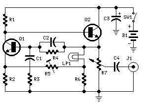
1KHz Sinewave Generators
This circuit generates a stable 1 kHz sine wave using the inverted Wien bridge configuration (C1-R3 & C2-R4). It features a variable output, low distortion, and low output impedance to ensure good overload capability. A small filament lamp provides a...
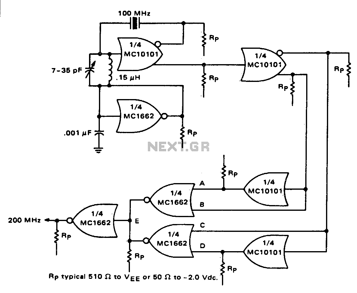
High frequency crystal oscillator
One section of the MC10101 is configured as a 100 MHz crystal oscillator, with the crystal placed in series within the feedback loop. An LC tank circuit is utilized to tune the 100 MHz harmonic of the crystal, which can...
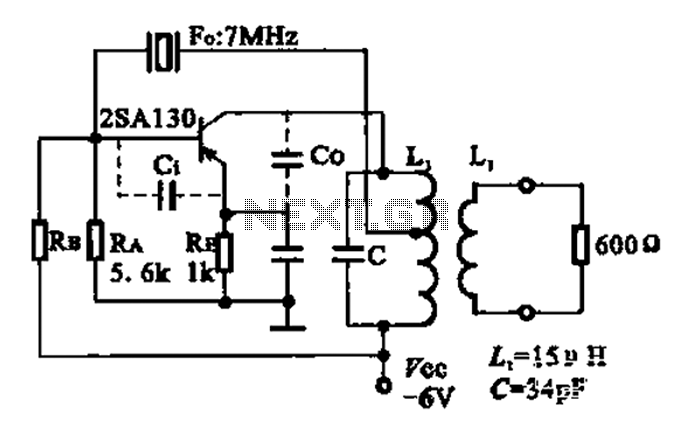
7MHz high frequency carrier oscillator
The 2SA130 transistor is used in an oscillator circuit with an oscillation frequency of 7 MHz. The power supply voltage is 6V, and the load is a frequency-selective resonant circuit with a quality factor of 600.
The circuit utilizes the 2SA130...
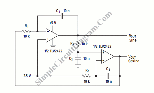
Quadrature Sinewave Oscillator
A quadrature oscillator is a type of phase shift oscillator that produces two sine wave signals, with one signal shifted by 90 degrees from the other.
The quadrature oscillator is commonly used in various applications such as signal processing, communications, and...
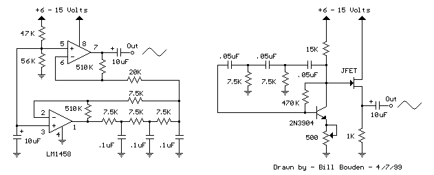
Sinewave Generator schematics
The two circuits below illustrate generating low frequency sinewaves by shifting the phase of the signal through an RC network so that oscillation occurs where the total phase shift is 360 degrees. The transistor circuit on the right produces a...
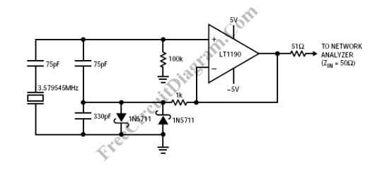
High Frequency Colpitts Crystal Oscillator
Op-amps have been widely used in low-frequency oscillators.
Op-amps, or operational amplifiers, are versatile components frequently utilized in the design of low-frequency oscillators. These devices are capable of generating periodic waveforms, such as sine, square, or triangular waves, which are essential...

High frequency switch
The 2N4391 features a low ON resistance of 30 ohms and a high OFF impedance of less than 0 pF when in the off state. With appropriate layout and an optimal switch configuration, the stated performance can be easily attained.
The...
egan fet silicon power shoot out volume 10 high frequency resonant converters
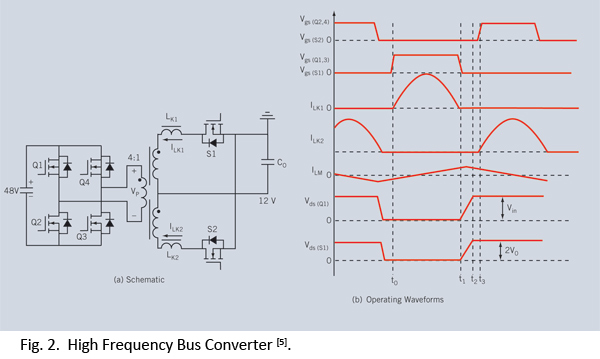
Distributed power systems are commonly used in telecommunications, networking, and high-end server applications, utilizing a 48 V bus voltage derived from the telecom industry. This 48 V bus supplies several isolated point-of-load (POL) converters that power the end loads, with...