


Safety Measures in Constructing EMG Amplifiers
#EMG
#biomedical
#gain
#forearm muscles
#National Instruments
#signal measurement
#medical instrumentation
#electrophysiology
#sensor interface
#low-noise
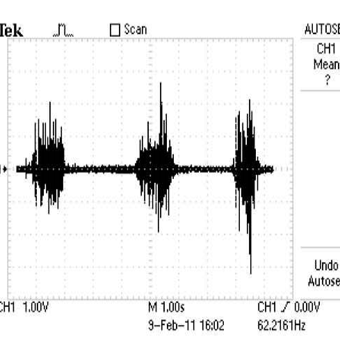
Description: The project involves constructing two similar EMG circuits with different gain settings to measure electromyography (EMG) signals from two forearm muscles: the Flexor Digitorum Superficialis (FDS) and the Extensor Carpi Radialis Longus (ECRL). The outputs from these circuits will be connected directly to a National Instruments SCC-68 connector block, interfacing with a PCI-6221 data acquisition (DAQ) system and a computer running LabVIEW 8.6 software. The objective is to correlate the EMG signals from the forearm muscles with hand grip strength, measured while gripping a hand dynamometer. Included are the EMG waveform from the constructed circuit for the FDS muscle, the circuit schematic, and a brief experiment to analyze the relationship between EMG frequency and hand grip strength.
The project focuses on the design and implementation of two electromyography (EMG) circuits, tailored to capture and analyze the electrical activity of the Flexor Digitorum Superficialis (FDS) and Extensor Carpi Radialis Longus (ECRL) muscles. The circuits are designed with varying gain levels to optimize the signal output for each muscle, ensuring accurate readings of the EMG signals.
The EMG signals are routed to a National Instruments SCC-68 connector block, which serves as a bridge to the PCI-6221 data acquisition system. This DAQ system is integrated with a computer that operates LabVIEW 8.6, a platform for data visualization and analysis. The LabVIEW environment facilitates real-time monitoring and processing of the EMG signals, allowing for immediate feedback during experimental trials.
The primary goal of this project is to establish a correlation between the EMG signals recorded from the forearm muscles and the hand grip strength, which is quantified using a hand dynamometer. The experimental setup involves participants gripping the dynamometer while EMG data is collected, providing insights into muscle activation patterns related to grip strength.
Included in the project documentation are the EMG waveform data collected from the FDS muscle, along with the specific circuit schematic used for its measurement. Additionally, a concise experimental analysis is presented to examine the relationship between the frequency of the EMG signals and the corresponding grip strength, contributing to a better understanding of muscle function and performance.
Overall, this project aims to enhance the understanding of muscular activity in relation to physical strength, providing valuable data for applications in rehabilitation, sports science, and ergonomics.My project is about constructing two similar EMG circuits (differing in gain) to measure EMG from two forearm muscles called the Flexor Digitorum Superficialis (FDS) and Extensor Carpi Radialis Longus (ECRL). The outputs from the EMG circuits will be connected directly to a National Instrum ents SCC-68 Connector block with a PCI-6221 DAQ and computer running Labview 8. 6 software. The purpose of this project is to related the EMG signals from the forearm muscles to hand grip strength. Experimental measurements from the EMG are to be taken while im gripping a hand dynamometer. I have included the EMG waveform from the circuit I have constructed to measure EMG from the Flexor Digitorum Superficialis muscle.
I have also included the circuit schematic I have used together with a short experiment I conducted to find the relationship between EMG frequency and hand grip strength. 6180. EMG_circuit. pdf All content and materials on this site are provided "as is". TI and its respective suppliers and providers of content make no representations about the suitability of these materials for any purpose and disclaim all warranties and conditions with regard to these materials, including but not limited to all implied warranties and conditions of merchantability, fitness for a particular purpose, title and non-infringement of any third party intellectual property right.
TI and its respective suppliers and providers of content make no representations about the suitability of these materials for any purpose and disclaim all warranties and conditions with respect to these materials. No license, either express or implied, by estoppel or otherwise, is granted by TI. Use of the information on this site may require a license from a third party, or a license from TI. Content on this site may contain or be subject to specific guidelines or limitations on use. All postings and use of the content on this site are subject to the Terms of Use of the site; third parties using this content agree to abide by any limitations or guidelines and to comply with the Terms of Use of this site.
TI, its suppliers and providers of content reserve the right to make corrections, deletions, modifications, enhancements, improvements and other changes to the content and materials, its products, programs and services at any time or to move or discontinue any content, products, programs, or services without notice.
The project focuses on the design and implementation of two electromyography (EMG) circuits, tailored to capture and analyze the electrical activity of the Flexor Digitorum Superficialis (FDS) and Extensor Carpi Radialis Longus (ECRL) muscles. The circuits are designed with varying gain levels to optimize the signal output for each muscle, ensuring accurate readings of the EMG signals.
The EMG signals are routed to a National Instruments SCC-68 connector block, which serves as a bridge to the PCI-6221 data acquisition system. This DAQ system is integrated with a computer that operates LabVIEW 8.6, a platform for data visualization and analysis. The LabVIEW environment facilitates real-time monitoring and processing of the EMG signals, allowing for immediate feedback during experimental trials.
The primary goal of this project is to establish a correlation between the EMG signals recorded from the forearm muscles and the hand grip strength, which is quantified using a hand dynamometer. The experimental setup involves participants gripping the dynamometer while EMG data is collected, providing insights into muscle activation patterns related to grip strength.
Included in the project documentation are the EMG waveform data collected from the FDS muscle, along with the specific circuit schematic used for its measurement. Additionally, a concise experimental analysis is presented to examine the relationship between the frequency of the EMG signals and the corresponding grip strength, contributing to a better understanding of muscle function and performance.
Overall, this project aims to enhance the understanding of muscular activity in relation to physical strength, providing valuable data for applications in rehabilitation, sports science, and ergonomics.My project is about constructing two similar EMG circuits (differing in gain) to measure EMG from two forearm muscles called the Flexor Digitorum Superficialis (FDS) and Extensor Carpi Radialis Longus (ECRL). The outputs from the EMG circuits will be connected directly to a National Instrum ents SCC-68 Connector block with a PCI-6221 DAQ and computer running Labview 8. 6 software. The purpose of this project is to related the EMG signals from the forearm muscles to hand grip strength. Experimental measurements from the EMG are to be taken while im gripping a hand dynamometer. I have included the EMG waveform from the circuit I have constructed to measure EMG from the Flexor Digitorum Superficialis muscle.
I have also included the circuit schematic I have used together with a short experiment I conducted to find the relationship between EMG frequency and hand grip strength. 6180. EMG_circuit. pdf All content and materials on this site are provided "as is". TI and its respective suppliers and providers of content make no representations about the suitability of these materials for any purpose and disclaim all warranties and conditions with regard to these materials, including but not limited to all implied warranties and conditions of merchantability, fitness for a particular purpose, title and non-infringement of any third party intellectual property right.
TI and its respective suppliers and providers of content make no representations about the suitability of these materials for any purpose and disclaim all warranties and conditions with respect to these materials. No license, either express or implied, by estoppel or otherwise, is granted by TI. Use of the information on this site may require a license from a third party, or a license from TI. Content on this site may contain or be subject to specific guidelines or limitations on use. All postings and use of the content on this site are subject to the Terms of Use of the site; third parties using this content agree to abide by any limitations or guidelines and to comply with the Terms of Use of this site.
TI, its suppliers and providers of content reserve the right to make corrections, deletions, modifications, enhancements, improvements and other changes to the content and materials, its products, programs and services at any time or to move or discontinue any content, products, programs, or services without notice.
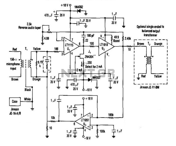
Low-Noise Audio Preamp
A low-noise LT1115 (Linear Technology, Inc.) operational amplifier is connected to a class-A buffer amplifier to create a variable gain (12-to-50 dB) microphone preamplifier. Total harmonic distortion (THD) is less than 0.01% across a frequency range from 80 Hz to...
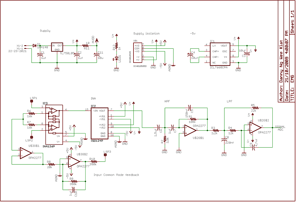
Electromyogram Monitor
Electrical potentials are generated by muscle when there is movement. This signal can be picked up by electrodes to form EMG. For my final year project, I did an amplifier and signal conditioning circuit for EMG. Attached below is the...
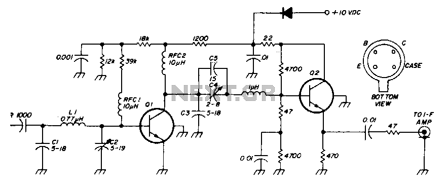
Low-noise 30Mhz preamplifier
The low-noise preamplifier features a noise figure of 1 dB at 30 MHz and a 3 dB bandwidth of 10 MHz. The gain is 19 dB. The total current drain with a +10 volt supply is 13 mA. The resistors...
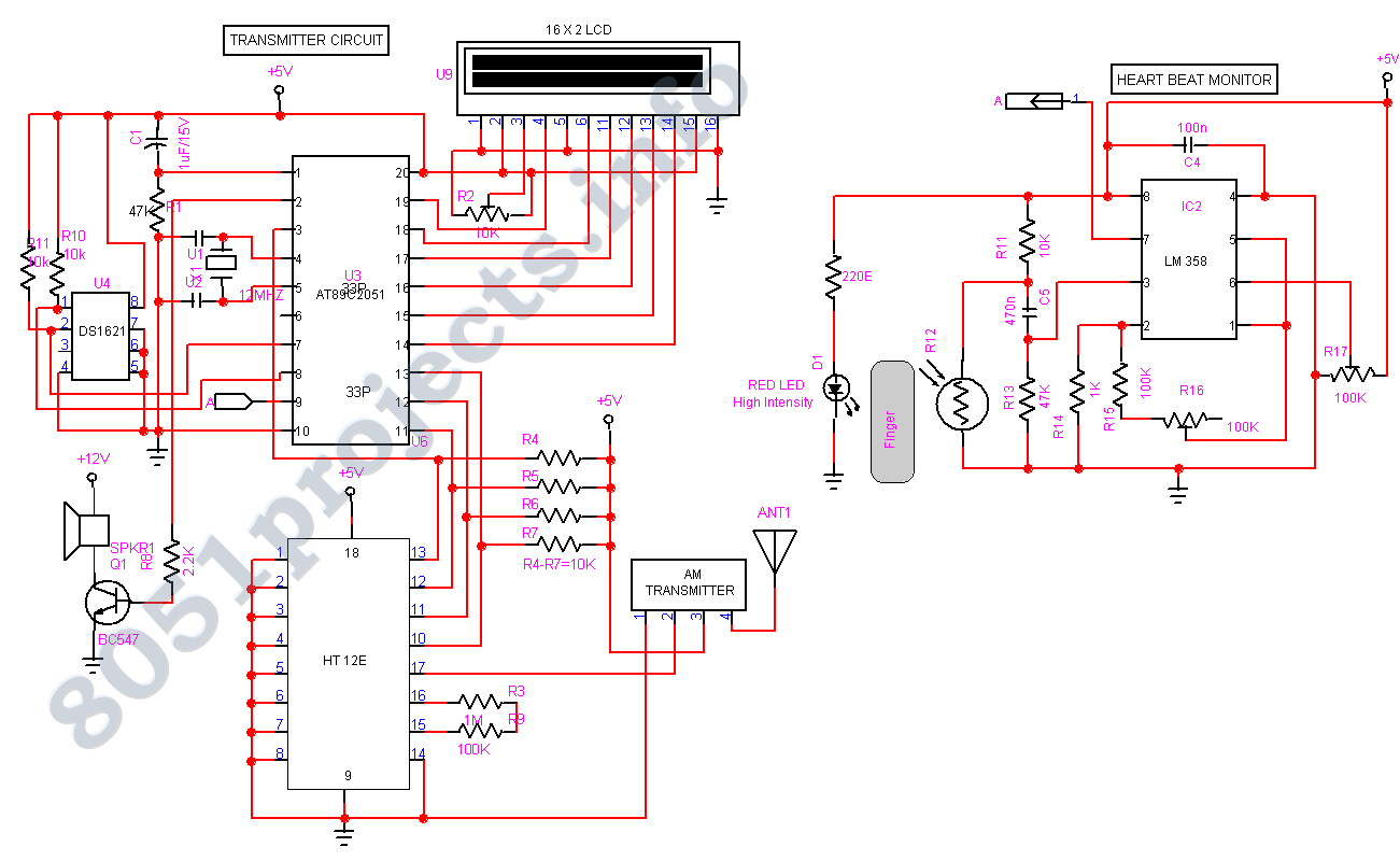
Biomedical Monitoring circuit AT89C2051
In spite of the improvement of communication link and despite all progress in advanced communication technologies, there are still very few functioning commercial wireless monitoring systems, which are most off-line, and there are still a number of issues to deal...
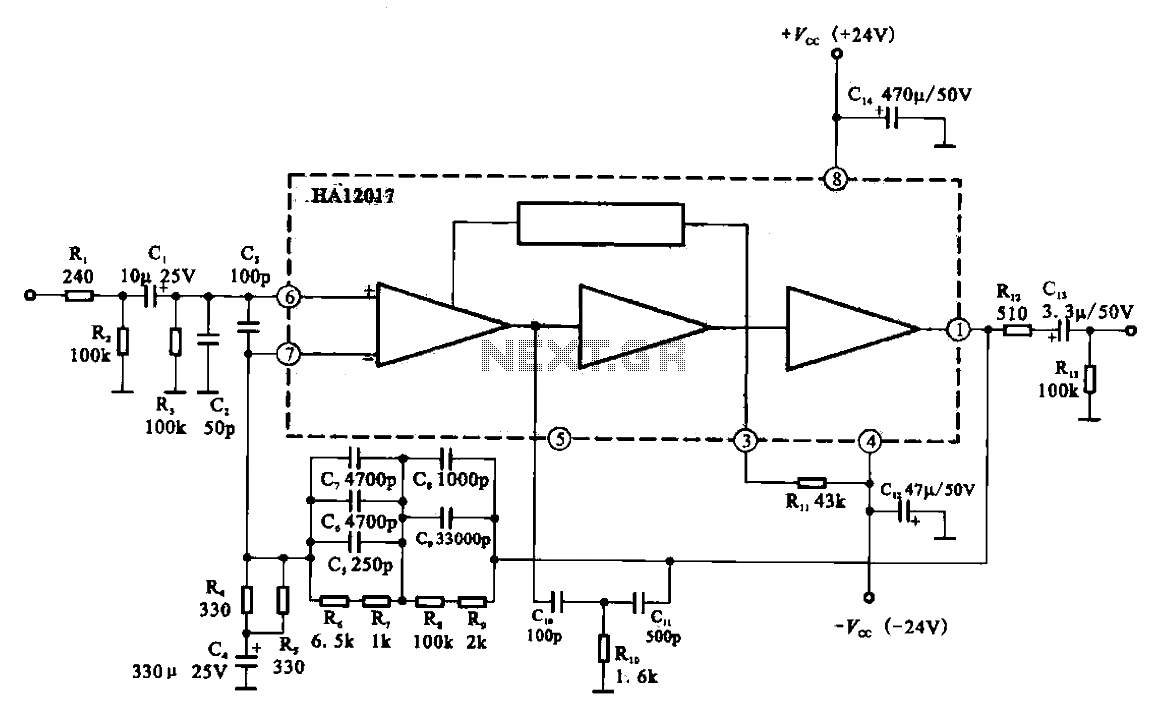
Low-noise preamplifier circuit
Low-noise preamplifier circuit. This circuit demonstrates a typical low-noise preamplifier design, which can be utilized to amplify signals from sources such as magnetic heads and microphones within audio applications. The input signal is coupled through a capacitor and subsequently passed...
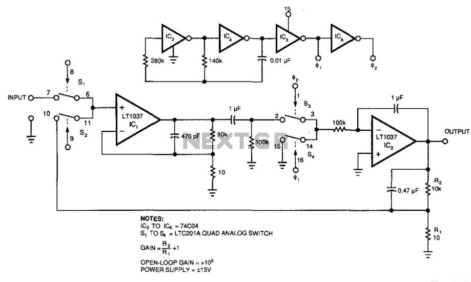
Low-Drift/Low-Noise Dc Amplifier
Figure 39-2's circuit combines a low-noise operational amplifier, IC1, with a chopper-based carrier-modulation scheme to achieve a low-noise, low-drift DC amplifier whose performance exceeds any currently available monolithic amplifier. The amplifier's offset is less than 1 mV, and its drift...
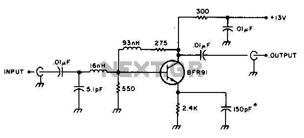
Low-noise broadband amplifier
The amplifier delivers a gain of 10 dB across a frequency range of 10-600 MHz and features a 1-to-1 impedance match at 50 ohms. The BFR91 transistor exhibits a noise figure of 1 dB at 500 MHz. The circuit operates...
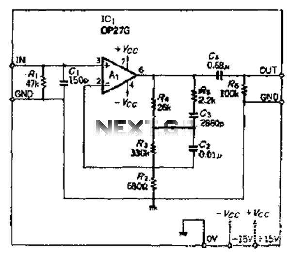
For low-noise amplifier OP amplifier RIAA compensation
A common telecoil follows the MM formula (magnetic-acting) and has an impedance of approximately 600 ohms to effectively receive signals. It is necessary to reduce the impedance in the high-frequency segment, which is achieved by placing a 150pF capacitor in...
Low-noise preamplifier circuit
Low-noise preamplifier circuit. This circuit demonstrates a typical low-noise preamplifier design, which can be utilized to amplify signals from sources such as magnetic heads and microphones within audio applications. The input signal is coupled through a capacitor and subsequently passed...