


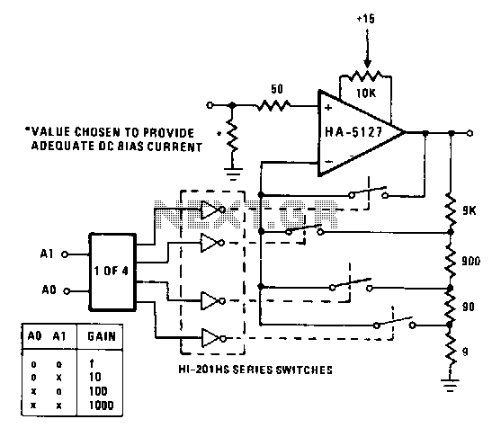
You can set 1 10 100 1000 times magnification programmable amplifier
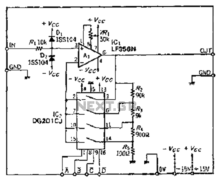
Description: The Jiu zoom magnification circuit operates as an inverted feedback circuit, where the voltage division ratio is determined by a factor ranging from 2 to 5. This ratio establishes the partial pressure ratio, which can be selected through an external signal. For instance, to achieve a partial pressure ratio of 1/10, a resistor divider circuit with a configuration of 90 kΩ and 10 kΩ can be employed. Each magnification setting necessitates specific calculations for the circuit diagram parameters. The chosen resistor array is designed to adapt to the resistor divider, ensuring high precision in applications. The circuit incorporates an input protection mechanism, which includes components such as D- and Dz, allowing for operation without compromising the integrity of the feedback circuit. To adjust the feedback circuit's division ratio for variable gain, a small input bias current is essential. The circuit utilizes a FET input type operational amplifier, which functions as a variable gain DC amplifier and requires careful offset adjustment throughout its operation.
The Jiu zoom magnification circuit exemplifies a sophisticated design that leverages inverted feedback mechanisms to achieve variable gain based on external signal inputs. The voltage division ratio, set between 2 and 5, allows for flexibility in applications requiring different levels of magnification. The resistor divider configuration, specifically using a 90 kΩ and 10 kΩ resistor pair, is critical for establishing the desired partial pressure ratio. This ratio can be finely tuned by adjusting the resistor values, which directly influence the output characteristics of the circuit.
In high-precision applications, the selection of the resistor array is paramount, as it must ensure minimal deviation from the expected values. The inclusion of input protection components, such as diodes D- and Dz, enhances the circuit's reliability, safeguarding it against potential overvoltage conditions and ensuring stable operation during surgical procedures.
Moreover, the circuit's ability to modify the feedback division ratio is facilitated by the introduction of a small input bias current. This feature is particularly important for maintaining the integrity of the gain settings across various operational scenarios. The use of a FET input type operational amplifier is a strategic choice, as it provides high input impedance and low noise characteristics, essential for maintaining signal fidelity in variable gain applications. The requirement for offset adjustment underscores the need for precision in the overall circuit design, ensuring that the output remains consistent and accurate throughout its operational range.
Overall, the Jiu zoom magnification circuit presents a well-engineered solution for applications demanding variable gain and high precision, with robust design elements that enhance its functionality and reliability. Because the ball Jiu zoom magnification circuit is inverted feedback circuit voltage division ratio of the number of wells by the clamor of 2 to 5 to determine the partial pres sure ratio of the provision, the magnification selected by an external signal number. For example, If you need to d 10, in order to make partial pressure ratio of 1/10 can be used 90kQ: iokQ resistor divider circuit © in this order for each magnification to calculate the number of the circuit diagram parameters are derived. Since the resistor array selected with the adaptation resistor divider, so when the application objects requiring high precision, the circuit can be used Bong port input crown - and D-, Dz input protection circuit is used in the instrument during surgery circuit also without the crown, and D, Dz, in order to change the feedback circuit song dividing ratio to obtain variable gain, should be used before a small input bias current.
FET input type OP soul is in the mouth is a variable gain DC amplifier requires offset condensed whole circuit, the choice of the most
The Jiu zoom magnification circuit exemplifies a sophisticated design that leverages inverted feedback mechanisms to achieve variable gain based on external signal inputs. The voltage division ratio, set between 2 and 5, allows for flexibility in applications requiring different levels of magnification. The resistor divider configuration, specifically using a 90 kΩ and 10 kΩ resistor pair, is critical for establishing the desired partial pressure ratio. This ratio can be finely tuned by adjusting the resistor values, which directly influence the output characteristics of the circuit.
In high-precision applications, the selection of the resistor array is paramount, as it must ensure minimal deviation from the expected values. The inclusion of input protection components, such as diodes D- and Dz, enhances the circuit's reliability, safeguarding it against potential overvoltage conditions and ensuring stable operation during surgical procedures.
Moreover, the circuit's ability to modify the feedback division ratio is facilitated by the introduction of a small input bias current. This feature is particularly important for maintaining the integrity of the gain settings across various operational scenarios. The use of a FET input type operational amplifier is a strategic choice, as it provides high input impedance and low noise characteristics, essential for maintaining signal fidelity in variable gain applications. The requirement for offset adjustment underscores the need for precision in the overall circuit design, ensuring that the output remains consistent and accurate throughout its operational range.
Overall, the Jiu zoom magnification circuit presents a well-engineered solution for applications demanding variable gain and high precision, with robust design elements that enhance its functionality and reliability. Because the ball Jiu zoom magnification circuit is inverted feedback circuit voltage division ratio of the number of wells by the clamor of 2 to 5 to determine the partial pres sure ratio of the provision, the magnification selected by an external signal number. For example, If you need to d 10, in order to make partial pressure ratio of 1/10 can be used 90kQ: iokQ resistor divider circuit © in this order for each magnification to calculate the number of the circuit diagram parameters are derived. Since the resistor array selected with the adaptation resistor divider, so when the application objects requiring high precision, the circuit can be used Bong port input crown - and D-, Dz input protection circuit is used in the instrument during surgery circuit also without the crown, and D, Dz, in order to change the feedback circuit song dividing ratio to obtain variable gain, should be used before a small input bias current.
FET input type OP soul is in the mouth is a variable gain DC amplifier requires offset condensed whole circuit, the choice of the most
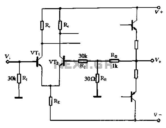
A feedback circuit and the differential input stage bias circuit is provided separately
The circuit utilizes the configuration illustrated in Figure 1-36, with the feedback circuit and bias circuit implemented separately. The feedback resistor, Rfl, is approximately 30 ohms. To maintain the desired amplification, the resistor R queue is set to 1 kilo-ohm...
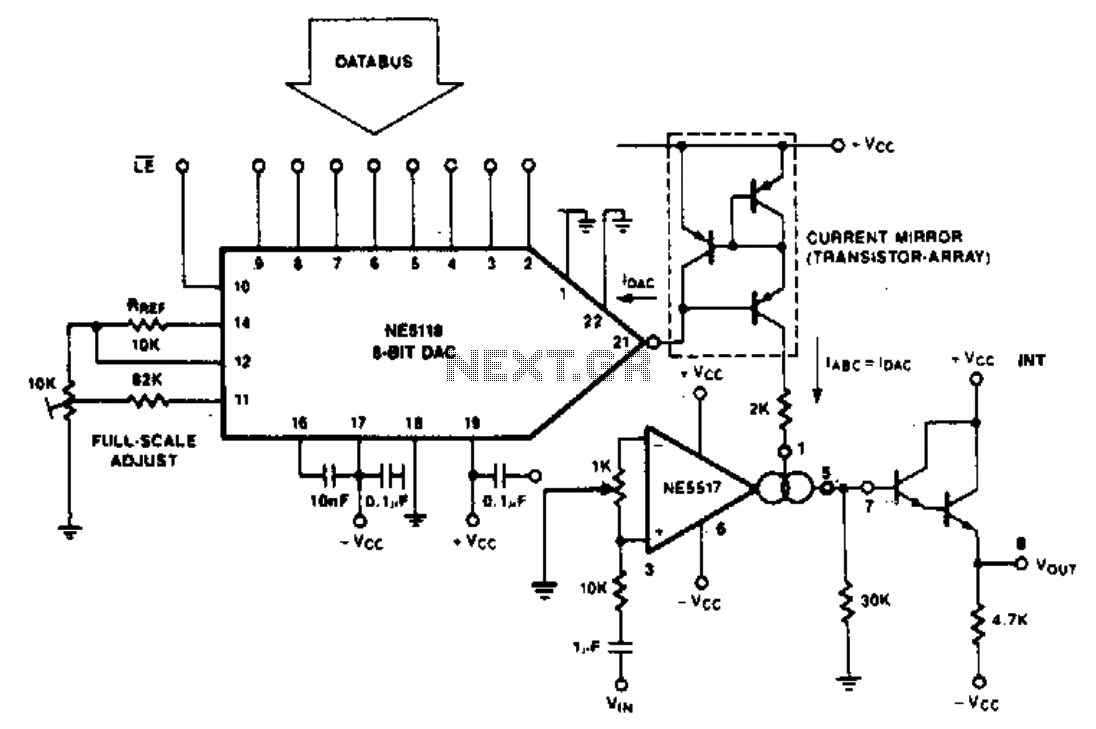
Programable amplifier
The purpose of the following application is to demonstrate how the NE5517 operates in conjunction with a DAC. The application utilizes the NE5118, an 8-bit DAC with current output, featuring an input register that makes this device fully micro-compatible. The...
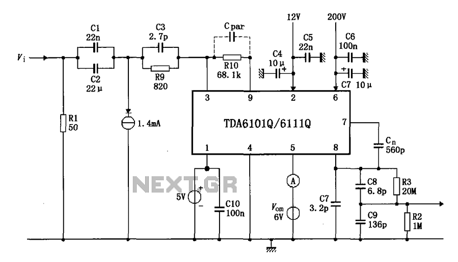
Test circuit diagram with feedback factor of 1 83 DA6101Q 6111Q
The test circuit features a feedback factor of 1/83 utilizing the DA6101Q/6111Q. The input signal is fed through a network comprising resistors R1 and R9, and capacitors C1, C2, and C3, entering the TDA6101Q, which includes three pins for the...
Programmable-amplifier
A circuit may often be required to perform multiple functions. In these cases, the variable gain configuration of the circuit can be particularly advantageous. This programmable gain stage utilizes CMOS analog switches to modify the feedback amount, thereby adjusting the...