


arduino How to make a clean amplified microphone analog to digital conversion
#arduino
#electret mic
#opamp
#ADC
#analogRead
#microcontroller
#signal processing
#noise reduction
#audio amplification
#10-bit conversion
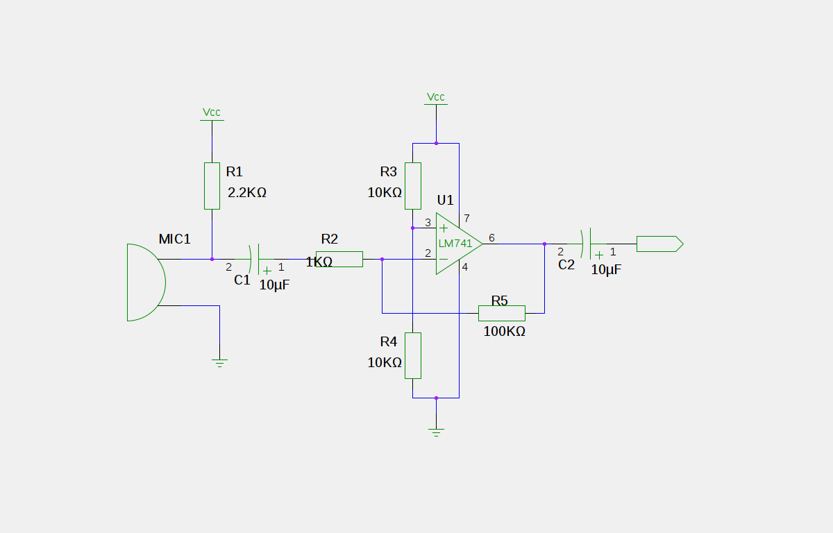
Description: An electret microphone has been connected to an operational amplifier (op-amp), with the output directed to an Arduino microcontroller. The analog-to-digital converter (ADC) on the microcontroller converts a voltage range of 0 to 5 volts into a 10-bit number, ranging from 0 to 1023. However, the output from the op-amp and the Arduino is not clean. The analogRead() function on the Arduino consistently returns a non-zero value, even in the absence of sound from the microphone. While the readings respond accurately to sound, the baseline "zero" value is not actually zero and often fluctuates, affecting the readings. A capacitor (C2) is in place, providing approximately 2 volts. There is a concern regarding potential current trapped in the feedback loop between pin 2 and pin 6 of the op-amp. It has been suggested that the presence of C2 indicates the output of the preamp should oscillate around 0V, rather than 2. Additionally, it was recommended to insert a Schottky diode between the preamp C2 and the Arduino input to eliminate negative voltages. Another capacitor was added between the analog input and ground to smooth the signal, reducing fluctuations in the VU meter. It was advised to remove the output capacitor, as the circuit was intended to produce a signal around zero volts, while the microcontroller expects a signal centered around half of Vdd. Electret microphones typically require significant gain, with a suggested voltage gain of around 1000. The gain in the circuit is determined by the ratio of resistors R5 to R2, but the stated values would yield a gain of 5000, which is excessive for a single op-amp stage. This high gain would amplify any offset voltage significantly, and the op-amp may not perform adequately across the full frequency range. It was noted that at a gain-bandwidth product of 1 MHz, the effective gain would be limited to below 200 Hz. The impedance seen by the microphone after the input capacitor should be larger than the microphone's impedance, and a value of 10 kΩ is more suitable than the previously mentioned 10 Ω. A recommendation was made to use two amplification stages with a gain of around 30 each, allowing for manageable gain across a reasonable frequency range while ensuring feedback functionality. Capacitive coupling between the stages is necessary to prevent the accumulation of input offset voltage. A total voltage gain of approximately 1000 is considered sufficient for a typical electret microphone. The circuit design emphasizes distributing gain across multiple stages, with each stage providing a gain of about 31, allowing for predictable and flat gain characteristics across the audio frequency range, given that the MCP6022 op-amp has a gain-bandwidth product of 10 MHz. The output DC offset is expected to be close to half of the supply voltage due to the low offset voltage of the op-amps used.
To achieve a clean output from the electret microphone circuit, it is essential to consider the following aspects:
1. **Microphone and Op-Amp Configuration**: The electret microphone should be connected to the op-amp in a way that optimizes gain and minimizes noise. The op-amp should be configured to provide sufficient gain without introducing excessive offset voltage.
2. **Gain Staging**: Employing multiple stages of amplification, each with a moderate gain (e.g., around 30), can help maintain signal integrity and prevent distortion. This approach allows for better control over the frequency response and reduces the likelihood of feedback issues.
3. **Capacitive Coupling**: Capacitors should be used between stages to block DC offsets while allowing AC signals to pass through. This prevents the accumulation of offset voltages across multiple stages, which can lead to inaccurate readings.
4. **Signal Conditioning**: Additional capacitors may be added at the output to smooth the signal further, reducing fluctuations in the readings on the Arduino. A Schottky diode can be utilized to clip negative voltages that are not useful for the application.
5. **Impedance Matching**: It is crucial to ensure that the impedance seen by the microphone is appropriate. Selecting resistor values that provide a higher impedance than the microphone's output will help improve performance, especially at lower frequencies.
6. **Testing and Calibration**: After implementing the circuit, it is advisable to test the system under various conditions to ensure that the output is stable and responsive to sound. Calibration may be necessary to fine-tune the gain and offset settings.
By addressing these considerations, a more reliable and accurate microphone interface can be achieved, resulting in cleaner audio signals suitable for further processing by the Arduino microcontroller.Hooked up an electret mic into an opamp and gave output to my arduino microcontroller. The ADC on the microcontroller converts a range of 0 to 5 vV to a 10-bit number (0 to 1023). The problem is that the output from the latter two chips is not "clean". The analogRead() on the Arduino is always reading a non-zero value even when I make no noise in the mic. The reading reacts properly when I make noise, but the "zero" value is non-zero. Sometimes the "zero" value even flickers throwing off the reading all the time. Hopefully that made sense. Yes I have C2 in place. It`s about 2 volts. I dont know if this makes any sense: could it be that there is some current trapped( ) in the loop between pin 2 and 6, the output and inverting input Shubham Jul 10 `11 at 0:55 The presence of C2 means that the output of the preamp will be swinging around 0V - not 2. 5V which it is operating at internally. Majenko Jul 10 `11 at 8:49 One other thing - you may want to slip a little shottky diode in between the pre-amp C2 and the Arduino input - throw away those negative voltages that you really don`t care about.
One more thing I did was to add another capacitor between the analog input and ground to smooth the signal out a bit. Makes the VU meter a little less flickery. Majenko Jul 10 `11 at 8:53 Get rid of the output capacitor. That circuit was probably meant to produce a signal around zero, so the capacitor is there to block the 1/2 Vdd offset.
However, the microcontroller wants to see the signal centered around 1/2 Vdd, so just get rid of the capacitor. Microcphones do need a lot of gain. Electrets can be sensitive, but you still might need a voltage gain of 1000. The gain in your circuit is the ratio of R5 to R2, but this only works within limits of what the opamp can do.
The values you mentioned above would give you a gain of 5000. That`s a lot more than you should try to get from a single opamp stage. Not only will the offset voltage be multiplied by this gain, but the opamp won`t be able to provide that over the full frequency range. At 1 MHz gain-bandwidth, you`ll only get that gain somewhat below 200 Hz. Even a 1 mV input offset becomes 5V after amplification by 5000. R2 is also the impedance seen by the microphone after the input capacitor. You need this to be somewhat larger than the impedance of the microphone with its pullup and the input capacitor at the lowest frequency of interest.
10 © is way too small for that. 10 K © would be a better value. Try two stages with a gain of 30 or so for starters and see where that gets you. That`s a gain it can handle over reasonable frequencies with enough headroom left for the feedback to work. You also need to capacitively couple the two stages so that the input offset voltage does not accumulate thru all the stages.
This has a voltage gain of roughly 1000, which should be sufficient for a reasonable electret microphone. I may be a little too much, but its easy to add some attenuation. The topology is rather different from your circuit. The most important single thing to note is that it doesn`t try to produce the whole gain in one stage.
Each stage has a gain of about 31. That leaves plenty of gain headroom at the maximum audio frequency of 20 kHz for the feedback, so the gain will be nicely predictable and flat accross the audio frequency range since the MCP6022 has a typical gain-bandwidth product of 10 MHz. The limiting factor will most likely be the microphone. Unlike what I said before, the two stages do not need to be capacitively coupled to prevent the offset voltage accumulating along with the gain.
That is because in this circuit, each stage has only a DC gain of 1, so the final offset is only twice the opamp offset. These opamps have only 500uV offset, so the final offset is only 1mV due to the opamps. There will be more due to the mismatch of R3 and R4. In any case, the output DC will be plenty close enough to 1/2 the sup
To achieve a clean output from the electret microphone circuit, it is essential to consider the following aspects:
1. **Microphone and Op-Amp Configuration**: The electret microphone should be connected to the op-amp in a way that optimizes gain and minimizes noise. The op-amp should be configured to provide sufficient gain without introducing excessive offset voltage.
2. **Gain Staging**: Employing multiple stages of amplification, each with a moderate gain (e.g., around 30), can help maintain signal integrity and prevent distortion. This approach allows for better control over the frequency response and reduces the likelihood of feedback issues.
3. **Capacitive Coupling**: Capacitors should be used between stages to block DC offsets while allowing AC signals to pass through. This prevents the accumulation of offset voltages across multiple stages, which can lead to inaccurate readings.
4. **Signal Conditioning**: Additional capacitors may be added at the output to smooth the signal further, reducing fluctuations in the readings on the Arduino. A Schottky diode can be utilized to clip negative voltages that are not useful for the application.
5. **Impedance Matching**: It is crucial to ensure that the impedance seen by the microphone is appropriate. Selecting resistor values that provide a higher impedance than the microphone's output will help improve performance, especially at lower frequencies.
6. **Testing and Calibration**: After implementing the circuit, it is advisable to test the system under various conditions to ensure that the output is stable and responsive to sound. Calibration may be necessary to fine-tune the gain and offset settings.
By addressing these considerations, a more reliable and accurate microphone interface can be achieved, resulting in cleaner audio signals suitable for further processing by the Arduino microcontroller.Hooked up an electret mic into an opamp and gave output to my arduino microcontroller. The ADC on the microcontroller converts a range of 0 to 5 vV to a 10-bit number (0 to 1023). The problem is that the output from the latter two chips is not "clean". The analogRead() on the Arduino is always reading a non-zero value even when I make no noise in the mic. The reading reacts properly when I make noise, but the "zero" value is non-zero. Sometimes the "zero" value even flickers throwing off the reading all the time. Hopefully that made sense. Yes I have C2 in place. It`s about 2 volts. I dont know if this makes any sense: could it be that there is some current trapped( ) in the loop between pin 2 and 6, the output and inverting input Shubham Jul 10 `11 at 0:55 The presence of C2 means that the output of the preamp will be swinging around 0V - not 2. 5V which it is operating at internally. Majenko Jul 10 `11 at 8:49 One other thing - you may want to slip a little shottky diode in between the pre-amp C2 and the Arduino input - throw away those negative voltages that you really don`t care about.
One more thing I did was to add another capacitor between the analog input and ground to smooth the signal out a bit. Makes the VU meter a little less flickery. Majenko Jul 10 `11 at 8:53 Get rid of the output capacitor. That circuit was probably meant to produce a signal around zero, so the capacitor is there to block the 1/2 Vdd offset.
However, the microcontroller wants to see the signal centered around 1/2 Vdd, so just get rid of the capacitor. Microcphones do need a lot of gain. Electrets can be sensitive, but you still might need a voltage gain of 1000. The gain in your circuit is the ratio of R5 to R2, but this only works within limits of what the opamp can do.
The values you mentioned above would give you a gain of 5000. That`s a lot more than you should try to get from a single opamp stage. Not only will the offset voltage be multiplied by this gain, but the opamp won`t be able to provide that over the full frequency range. At 1 MHz gain-bandwidth, you`ll only get that gain somewhat below 200 Hz. Even a 1 mV input offset becomes 5V after amplification by 5000. R2 is also the impedance seen by the microphone after the input capacitor. You need this to be somewhat larger than the impedance of the microphone with its pullup and the input capacitor at the lowest frequency of interest.
10 © is way too small for that. 10 K © would be a better value. Try two stages with a gain of 30 or so for starters and see where that gets you. That`s a gain it can handle over reasonable frequencies with enough headroom left for the feedback to work. You also need to capacitively couple the two stages so that the input offset voltage does not accumulate thru all the stages.
This has a voltage gain of roughly 1000, which should be sufficient for a reasonable electret microphone. I may be a little too much, but its easy to add some attenuation. The topology is rather different from your circuit. The most important single thing to note is that it doesn`t try to produce the whole gain in one stage.
Each stage has a gain of about 31. That leaves plenty of gain headroom at the maximum audio frequency of 20 kHz for the feedback, so the gain will be nicely predictable and flat accross the audio frequency range since the MCP6022 has a typical gain-bandwidth product of 10 MHz. The limiting factor will most likely be the microphone. Unlike what I said before, the two stages do not need to be capacitively coupled to prevent the offset voltage accumulating along with the gain.
That is because in this circuit, each stage has only a DC gain of 1, so the final offset is only twice the opamp offset. These opamps have only 500uV offset, so the final offset is only 1mV due to the opamps. There will be more due to the mismatch of R3 and R4. In any case, the output DC will be plenty close enough to 1/2 the sup
Expressive Arduino Midi Sequencer
This section of code outlines the main sequence of operation for the sequencer. A for loop is utilized to determine which step the sequencer is operating in. Within this loop, an address is generated using the assignByteToPins() function, which sends...
Glove circuit that lights up with a hand shake
The task involved testing the capacitive properties of food by connecting various edibles to an Arduino. This project, known as BeetBox, was developed by Scott Garner, a student at NYU-ITP, who designed an innovative musical instrument that uses beets as...
DOGM128 with Arduino Hardware
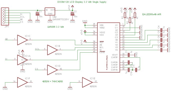
The DOGM graphics module should be connected to the Arduino board as illustrated. Pin 12 (MISO) of the Arduino board must remain unused. Furthermore, the DOGM graphics module requires an address line (A0), which can be connected to any output...
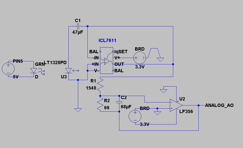
Arduino sampling code and circuit schematic
The code implementation discussed in the previous post has been initiated. To improve organization, the code has been modularized into functions, simplifying the overall structure. It is available along with the other code. Challenges were encountered in calculating averages while...
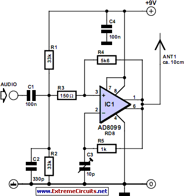
Opamp VHF FM Transmitter
Integrated circuits (ICs) that were previously too costly for hobbyists are now more affordably priced. An example is the AD8099 from Analog Devices, which is available for only a few pounds. The AD8099 is a very fast operational amplifier (op-amp)...
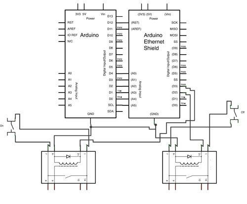
Programming
This article discusses the use of a Raspberry Pi to create a compact interface for controlling fireplaces through a home automation system, replacing a previous Arduino setup. The project aims to reduce bulkiness by placing the controller under the fireplace....
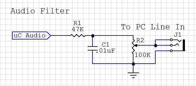
Arduino Audio DAC Options
DAC stands for Digital to Analog Converter. This article explores the code created by Michael Smith for a PWM-based DAC. The code has been modified to allow for the testing of various DAC options. A comparison is made between the...
Miniature Real-time Controller
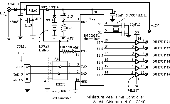
This is my long history the device that controls my home's night light, air-conditioner, etc. The device is a Miniature Real-time Controller. The circuit uses only three chips, a 89C2051, DS275 (or MAX232), and 74LS07 open collector driver. The scheduler...
ramped magnetic field circuit for a miniature mass spectrometer
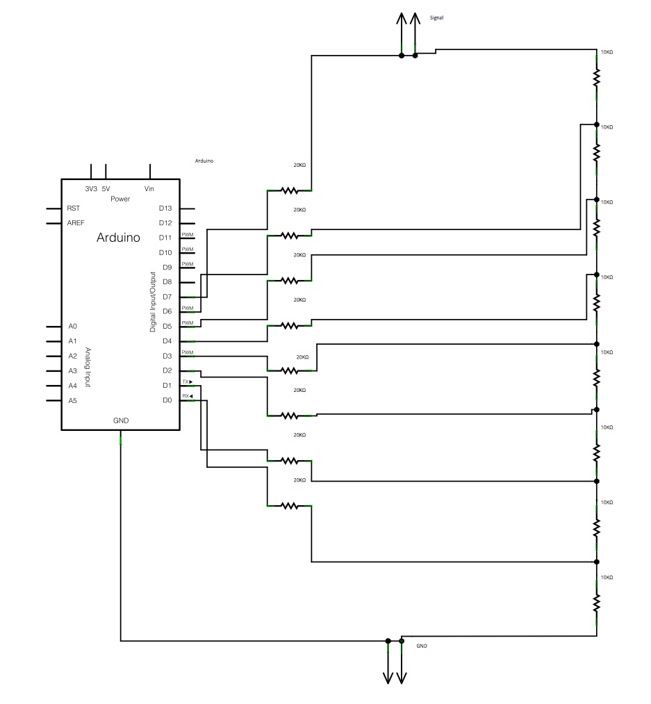
The main concept is to space the time intervals to increment the DAC output values. There are 256 levels since there are 8 digital outputs from the Arduino board. Therefore, for an 8-bit resolution and a 50-second ramp time, the...