


theremin as a capacitive sensing device
#theremin
#capacitive sensing
#Arduino
#MIDI
#proximity sensor
#musical instrument
#Processing
#Max
#Pd
#control signal
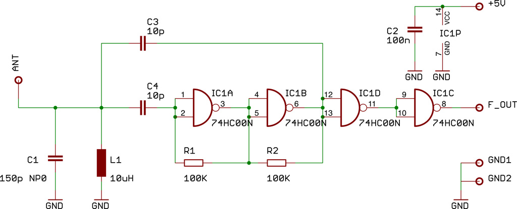
Description: This document presents a compact Theremin module designed to connect to an Arduino board, which outputs sound to a speaker or generates control signals such as MIDI or servo commands. The device serves not only as a musical instrument but also as various proximity sensors and pointing devices, and can interface with software like Processing, Max, or Pd. The Theremin module operates as a small LC type radio frequency oscillator that generates a radio wave, sending frequency signals to the Arduino board. The Arduino functions as an accurate frequency meter, converting frequency deviations into sound or control signals. A brief overview of the oscillator schematic reveals components L1 and C1, which form a resonator responsible for an oscillator frequency of approximately 4.1 MHz. Gates IC1A and IC1B constitute an analog amplifier block that amplifies the oscillator signal for feedback to the resonator. Capacitor C3 provides positive feedback, enabling steady oscillation. Gates D and C condition the wave into a digital logic level square wave signal for the Arduino board. Care should be taken when selecting components L1 and C1; C1 must be a ceramic capacitor of NP0 type (zero temperature coefficient), and L1 should be a high-Q inductor suitable for high frequency, such as Neosid 00612299, though a standard 10uH choke can suffice for initial tests. Due to potential frequency drift from ambient temperature changes, the circuit should be enclosed in a small plastic box. The antenna should not exceed one meter in length, with a ring of 1.5mm steel wire providing good mechanical stability to prevent swinging or vibration. Most drift and unwanted effects are compensated by software. It is important to note that all metal components, including USB cables, connected speakers, and computers, can be influenced by the RF signal, acting as antennas themselves. To measure the oscillator frequency, the output connects to digital input 5 of the Arduino board, which serves as an input for the ATmega's internal hardware Counter1 unit. When configured via software, the counter increments by one for each level change on that pin, occurring approximately 4 million times per second. The hardware Timer2 unit acts as a timebase to start and stop counting over a precise interval of 1/10 second. After this period, the counter reads about 410,000, providing a measurement resolution of 10Hz, sufficient to detect slight frequency deviations caused by the Theremin effect. The Counter1 unit, being a 16-bit counter, experiences several overflows during measurement, which are counted in the timebase section and compiled into a long integer result. The entire timing process occurs within an interrupt function triggered by Timer2 every 2 milliseconds. When the timebase period concludes, a global variable flag signals the main function of a new value's availability. Since only frequency differences—not absolute values—are of interest, subsequent values are subtracted from the initial frequency value after startup. An autocalibration process is conducted after a series of measurement cycles when the deviation falls below a specified threshold value, which can be customized according to the application.
The Theremin module's design integrates several key components that ensure its functionality and reliability. The LC oscillator is the heart of the system, with L1 and C1 determining the resonant frequency. The choice of components is critical; L1 should have a high quality factor (Q) to minimize losses and ensure stable oscillation. The feedback mechanism provided by C3 is essential for maintaining oscillation, while the Gates ICs amplify the signal to a usable level. The digital conditioning performed by Gates D and C is crucial for interfacing with the Arduino, allowing for digital signal processing.
The enclosure of the circuit is important not only for physical protection but also for minimizing the effects of environmental factors on the oscillator's frequency stability. The choice of antenna length and material also plays a significant role in the performance of the Theremin, as it directly influences the sensitivity and range of the device.
The measurement process utilizing the Arduino's hardware counters is an efficient method for capturing the rapid frequency changes characteristic of the Theremin effect. The implementation of an interrupt-driven approach allows for precise timing and measurement, ensuring that even minor frequency deviations are detected and processed. The calibration routine further enhances the accuracy of the device, allowing it to adapt to changing environmental conditions and maintain consistent performance.
Overall, the Theremin module exemplifies a sophisticated integration of analog and digital electronics, leveraging the capabilities of the Arduino platform to create a versatile musical and sensing instrument.Here we show a little Theremin module which plugs onto a Arduino Board that gives out the tune to a speaker or puts out the tune as control signal like MIDI, Servo etc. We were using this device not only as a musical instrument, various kinds of proximity sensors, pointing devices or as interface in combination with Processing, Max or Pd have been
build with this technique. The Theremin Module itself is as little LC type Radio frequency oscillator which generates a radio wave and gives out the frequency signal to the Arduino board. The Arduino itself acts in this case as a accurate frequency meter which transforms this frequency deviation into sound or control signals.
Since you will find numerous articles in the Web describing the principle of a Theremin we leave here only that brief description. If you have a look at the Oscillator schematic you see the components L1 and C1 that are forming a resonator responsible for the oscillator frequency of about 4.
1 Mhz. The Gates IC1A and IC1B are building an analog amplifier block which is rising the oscillator signal to be fed back to the resonator. Capacitor C3 put an amount of energy back to the input as positive feedback so that an steady oscillation occurs.
The Gates D and C are conditioning the wave into a digital logic level squarewave signal for the Arduino board Care must be taken in the choice of the parts L1 and C1. C1 must be a ceramic capacitor NP0 type (zero temperature coefficient) and L1 a high Q inductor suitable for high frequency such as a Neosid 00612299 but for the first test a standard 10uH Choke will do also the job.
Because the oscillator frequency tends to drift by ambient temperature changes the circuit should be capsuled in a little plastic box. The antenna length should be not longer than about one meter, good results can be obtained with a ring of 1, 5mm steel wire which provides also a good mechanical stability to avoid swinging or vibration.
Most of the drift or other unwanted side effects are compensated by the software. It must be noticed that also that all metal parts like usb cable, connected speaker, even the connected computer are loaded by the RF signal and tend to be hot so that they work as antenna as well. To measure the oscillator frequency the output is connected to digitalinput 5 of the Arduino Board. This pin has an alternate function as an input of the ATMEGA internal hardware Counter1 unit. If configured by software, every time a level change is present on that pin the counter is advanced by one.
That happens in our case about 4 million times a second. The hardware Timer2 unit is used as a timebase to start and stop counting in a interval of exactly 1/10 second. After that period the counter value reads about 410. 000 so we yield a measurement resolution of 10Hz which is what we need to see the slight frequency deviation caused by the Theremin effect.
Since the Counter1 unit is only a 16 Bit counter several overflows occur during the measurement. These overflows are counted in the timebase section to be assembled after the measurement period to a long int result. The whole timing is done in an interrupt function which is invoked by the timer2 all 2 milliseconds. If the end of a timebase period is reached a flag as a global variable is set to signal the main function the presence of a new value.
Since only the frequency differences not the absolute value are of interest for us, the consecutive values are substracted from the first frequency value after startup. An autocalibration to eliminate long term frequency drift is performed after a number of measurement cylces when the deviation is smaller then a certain threshold value.
The threshold value and the number of cycles to calibrate has to be customized to the application. /* Theremin Test * * Therremin with TTL Oscillator 4MHz * Timer1 for freauency measurement * Timer2 for gate time * connect Oscillator on digital pin
The Theremin module's design integrates several key components that ensure its functionality and reliability. The LC oscillator is the heart of the system, with L1 and C1 determining the resonant frequency. The choice of components is critical; L1 should have a high quality factor (Q) to minimize losses and ensure stable oscillation. The feedback mechanism provided by C3 is essential for maintaining oscillation, while the Gates ICs amplify the signal to a usable level. The digital conditioning performed by Gates D and C is crucial for interfacing with the Arduino, allowing for digital signal processing.
The enclosure of the circuit is important not only for physical protection but also for minimizing the effects of environmental factors on the oscillator's frequency stability. The choice of antenna length and material also plays a significant role in the performance of the Theremin, as it directly influences the sensitivity and range of the device.
The measurement process utilizing the Arduino's hardware counters is an efficient method for capturing the rapid frequency changes characteristic of the Theremin effect. The implementation of an interrupt-driven approach allows for precise timing and measurement, ensuring that even minor frequency deviations are detected and processed. The calibration routine further enhances the accuracy of the device, allowing it to adapt to changing environmental conditions and maintain consistent performance.
Overall, the Theremin module exemplifies a sophisticated integration of analog and digital electronics, leveraging the capabilities of the Arduino platform to create a versatile musical and sensing instrument.Here we show a little Theremin module which plugs onto a Arduino Board that gives out the tune to a speaker or puts out the tune as control signal like MIDI, Servo etc. We were using this device not only as a musical instrument, various kinds of proximity sensors, pointing devices or as interface in combination with Processing, Max or Pd have been
build with this technique. The Theremin Module itself is as little LC type Radio frequency oscillator which generates a radio wave and gives out the frequency signal to the Arduino board. The Arduino itself acts in this case as a accurate frequency meter which transforms this frequency deviation into sound or control signals.
Since you will find numerous articles in the Web describing the principle of a Theremin we leave here only that brief description. If you have a look at the Oscillator schematic you see the components L1 and C1 that are forming a resonator responsible for the oscillator frequency of about 4.
1 Mhz. The Gates IC1A and IC1B are building an analog amplifier block which is rising the oscillator signal to be fed back to the resonator. Capacitor C3 put an amount of energy back to the input as positive feedback so that an steady oscillation occurs.
The Gates D and C are conditioning the wave into a digital logic level squarewave signal for the Arduino board Care must be taken in the choice of the parts L1 and C1. C1 must be a ceramic capacitor NP0 type (zero temperature coefficient) and L1 a high Q inductor suitable for high frequency such as a Neosid 00612299 but for the first test a standard 10uH Choke will do also the job.
Because the oscillator frequency tends to drift by ambient temperature changes the circuit should be capsuled in a little plastic box. The antenna length should be not longer than about one meter, good results can be obtained with a ring of 1, 5mm steel wire which provides also a good mechanical stability to avoid swinging or vibration.
Most of the drift or other unwanted side effects are compensated by the software. It must be noticed that also that all metal parts like usb cable, connected speaker, even the connected computer are loaded by the RF signal and tend to be hot so that they work as antenna as well. To measure the oscillator frequency the output is connected to digitalinput 5 of the Arduino Board. This pin has an alternate function as an input of the ATMEGA internal hardware Counter1 unit. If configured by software, every time a level change is present on that pin the counter is advanced by one.
That happens in our case about 4 million times a second. The hardware Timer2 unit is used as a timebase to start and stop counting in a interval of exactly 1/10 second. After that period the counter value reads about 410. 000 so we yield a measurement resolution of 10Hz which is what we need to see the slight frequency deviation caused by the Theremin effect.
Since the Counter1 unit is only a 16 Bit counter several overflows occur during the measurement. These overflows are counted in the timebase section to be assembled after the measurement period to a long int result. The whole timing is done in an interrupt function which is invoked by the timer2 all 2 milliseconds. If the end of a timebase period is reached a flag as a global variable is set to signal the main function the presence of a new value.
Since only the frequency differences not the absolute value are of interest for us, the consecutive values are substracted from the first frequency value after startup. An autocalibration to eliminate long term frequency drift is performed after a number of measurement cylces when the deviation is smaller then a certain threshold value.
The threshold value and the number of cycles to calibrate has to be customized to the application. /* Theremin Test * * Therremin with TTL Oscillator 4MHz * Timer1 for freauency measurement * Timer2 for gate time * connect Oscillator on digital pin
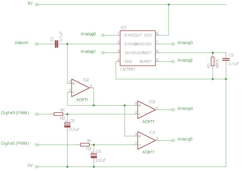
Arduino Eye Shield
The Arduino Eye Shield is a circuit board that can be plugged on top of the Arduino, enabling it to interpret analog video (PAL or NTSC) from a camera or other source. This provides the Arduino with visual capabilities, allowing...
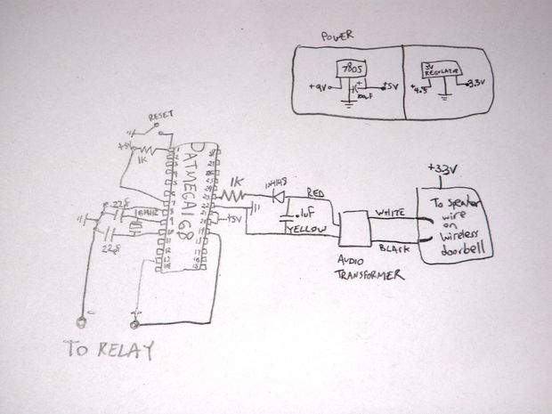
Personal Applause Sign
Construct a Hackduino board as outlined in the provided instructions. Detach the speaker from the wireless doorbell receiver, ensuring to leave as much wire connected to the receiver as possible.
The Hackduino board is a versatile and programmable platform that can...
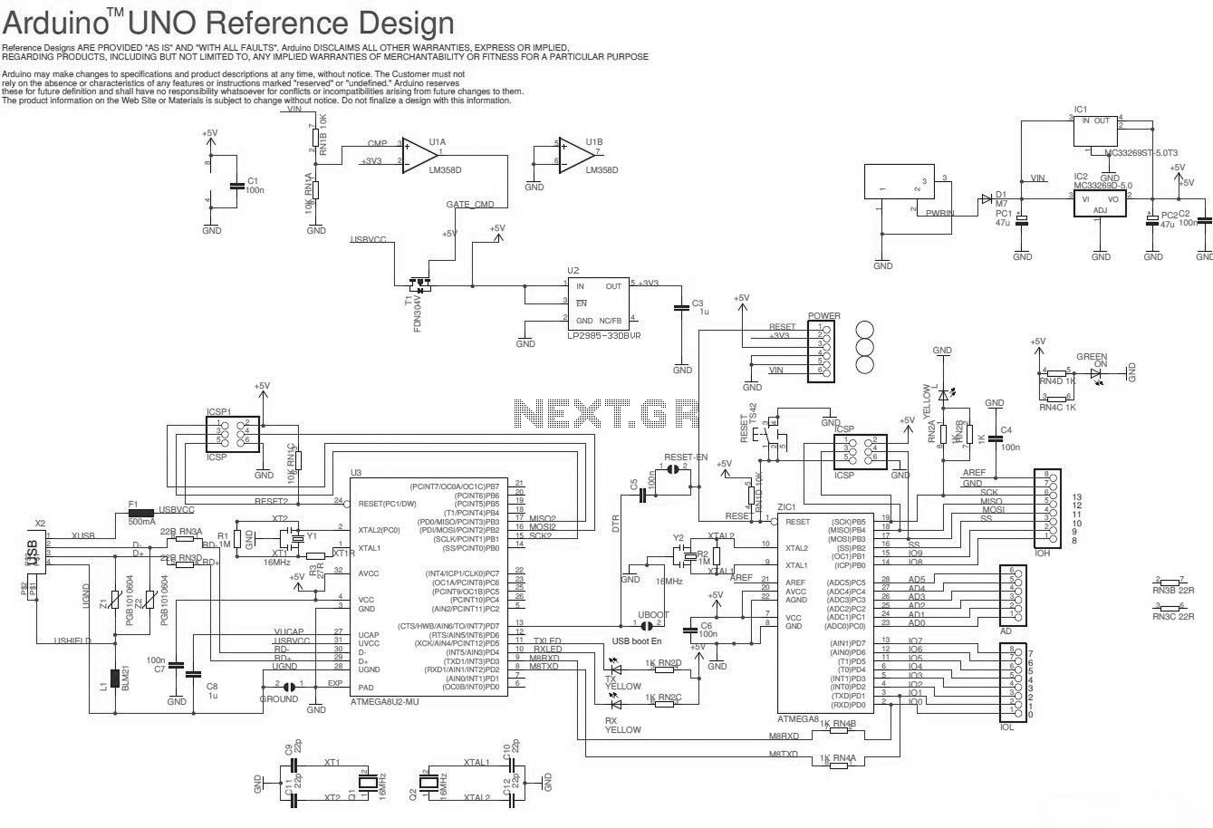
Arduino UNO
The Arduino Uno schematic diagram is available for viewing. The Arduino Uno is a microcontroller board that utilizes the ATmega328 chip. It features 14 digital input/output pins, of which 6 can be used as PWM outputs, and 6 analog input...
Arduino Make your own hardware
The Raspberry Pi single-board computer (SBC) has garnered significant attention for being a complete system priced under $50. However, it is not the most affordable computing device available. For only $13.50, a mini computer that connects to a PC's USB...
microcontroller complete code midi emulated ps 2 keyboard
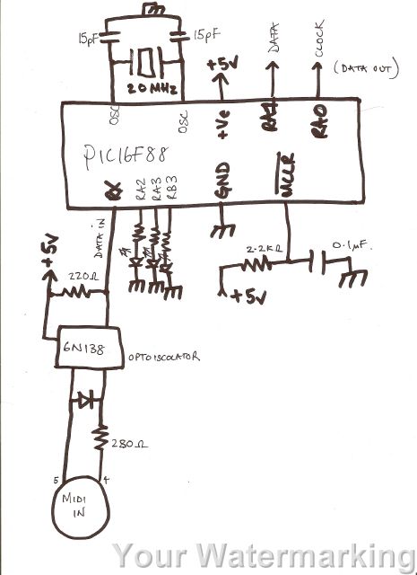
A code has been developed to process MIDI data received on the RX pin of the USART. It stores three bytes of data in a buffer, checks the first byte to determine if it is a MIDI "on" message (indicated...
Arduino Running A DC Motor and High Current Lamp
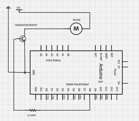
The BC547 transistor has a maximum operating current of 100 mA and a maximum voltage rating of 65 volts. When oriented with the label facing the viewer, the three terminals from left to right are collector, base, and emitter. It...
arduino How to make a clean amplified microphone analog to digital conversion
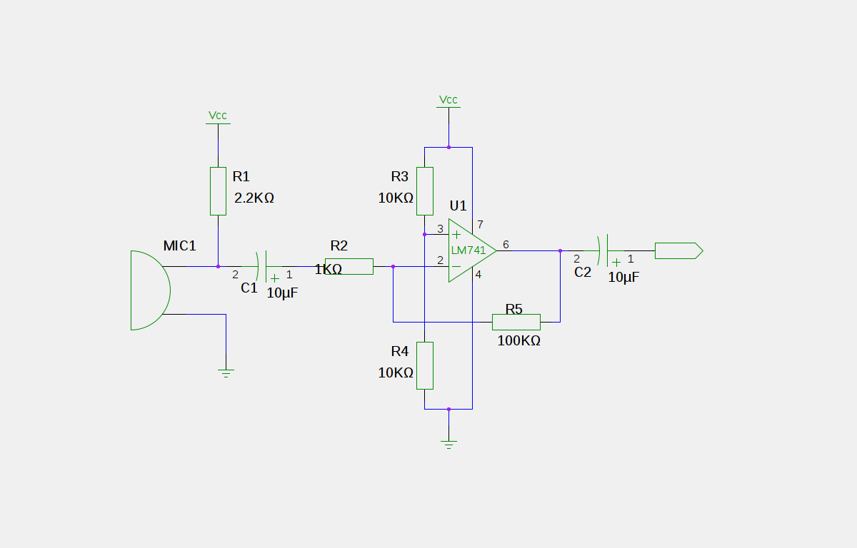
An electret microphone has been connected to an operational amplifier (op-amp), with the output directed to an Arduino microcontroller. The analog-to-digital converter (ADC) on the microcontroller converts a voltage range of 0 to 5 volts into a 10-bit number, ranging...
CSC231 Homework
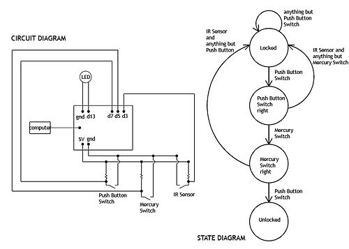
A diagram is requested to illustrate all hardware components used in a project and their connections. The diagram should depict the Arduino board as a box with lines indicating connections, arrows showing signal direction (inputs or outputs), and pin numbers....
Arduino Multiplexing
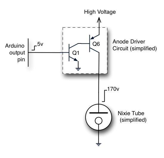
The Nixie tubes being utilized have 10 cathodes shaped like numerals and a screen-like anode. These are vintage Russian IN-12A tubes sourced from a reputable Ukrainian shop on eBay. Other types of Nixies may feature additional cathodes for displaying a...