


1996 GL1500 modulators interfering with audio
#power filter
#modulator
#GPS
#MP3 player
#radar detector
#oscilloscope
#noise reduction
#Aux Circuit
Description: A power filter is a device that is placed before devices such as GPS, MP3 players, or radar detectors connected to the auxiliary circuit. When properly used and installed, these filters can eliminate modulator noise from any system. Observing the waveform with an oscilloscope can provide significant insights into the operation of these systems. For instance, connecting the oscilloscope test lead to the headlight circuit will reveal a substantial waveform resembling a nearly vertical square wave. This can be likened to a toggle switch rapidly turning headlights on and off, averaging about 70% of the DC voltage during the "modulated" cycle.
Experiences with headlight modulators have highlighted issues with audio interference in intercom systems, particularly in motorcycles. After upgrading to a headlight modulator on a Gold Wing motorcycle, significant clicking noises were encountered in the audio system when the modulator was active. The manufacturer of the audio system was unhelpful, attributing the issue to a perceived fault in the audio design and recommending the addition of a large capacitor to the power source. However, this suggestion did not resolve the issue satisfactorily.
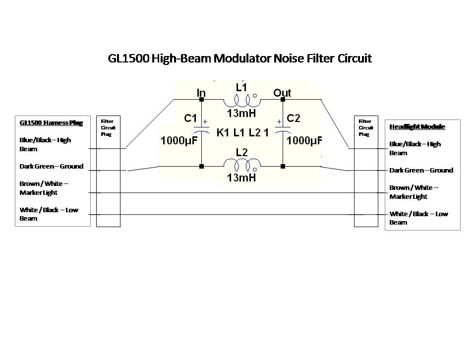
Further discussions with other manufacturers and community members revealed that modulator-induced noise is a common problem. A consensus emerged that isolating the voltage disruption caused by the modulator as close to the source as possible is crucial. The goal was to create a "filter" that could be easily integrated into the factory wiring for straightforward removal if necessary. A custom "filter" circuit was designed by a moderator from the AllAboutCircuits forum to address this issue.
The power filter circuit typically consists of capacitors, inductors, and resistors configured to attenuate high-frequency noise while allowing the desired DC voltage to pass through. The capacitors serve to shunt high-frequency noise to ground, while inductors can block high-frequency signals and allow low-frequency signals to pass. This combination can effectively reduce the interference experienced in audio systems when a headlight modulator is in operation.
The design of the filter should ensure compatibility with the existing wiring and components of the motorcycle, maintaining ease of installation and removal. Proper grounding and placement of the filter within the circuit are critical to achieving optimal performance. Testing the circuit with an oscilloscope before and after installation can provide valuable feedback on the effectiveness of the filter, helping to confirm that the modulator noise has been adequately suppressed.
In summary, the implementation of a power filter can significantly enhance the performance of auxiliary systems in motorcycles, particularly in mitigating the adverse effects of modulator-induced noise.A power filter is a device you put ahead of something like a GPS and MP3 player and or radar detector that you have run into the Aux Circuit. But these things used properly and properly installed will take the modulator noise out of any system.
If you were to observe what is happening with an oscilloscope, it would have a lot more meaning to you. Put the o`scope test lead on the headlight circuit and observe the waveform. It will be huge! Nearly a vertical square wave. Think of a toggle switch rapidly turn your headlights on/off at a rate so as to average about 70% of the DC voltage to the lights in the "modulated" cycle. IG ™ve been a motorcycle participant in several collisions with cars in my past. All of them shared the element that the driver of the car claimed, G I did not see youG . When I bought my Gold Wing, my first upgrade was a headlight modulator. I next upgraded my helmets with audio to allow rider to co-rider communication and immediately found that when the modulator was operating, there was a terribly annoying clicking noise on the intercom.
The manufacturer was totally uninterested in exploring a solution and claimed that my experience was the first theyG ™d ever heard of audio problems associated with modulator use. The manufacturerG ™s only guidance was that the Gold Wing must have a faulty audio/intercom design, and the best way to overcome this weakness would be to put a really big capacitor on the power source to the audio system.
They made it clear that any follow up on my problem would be under the condition of G fee for serviceG . If I ever buy another headlight modulator, I will consider other manufacturers first! I explored the situation with folks at J&M where I purchased my helmet audio. I spoke with manufacturers of other modulator systems and I spoke with folks at Electrical Connection.
It seems that I am not the first to have modulator induced noise in my audio system. I got some guidance from members on this forum who have had similar experiences and had considered various ways to resolve the audio noise. Finally I did extensive research using a variety of web resources, My summary of the resolution is NOT offered to provide an exactly repeatable solution that will be a fit to other modulator use scenarios, but as an educational perspective on the solvability of this type of problem.
Upon review of the symptoms by many of the folks I talked to ( except the manufacturer ), the consensus was that isolating the voltage disruption caused by the modulator induced current changes to the headlight, should be done as close to the source of the problem as possible. A primary design objective was to build a G filterG that could be plugged into the factory wiring to make removal simple, if needed.
The G filterG circuit, and build description below it, were custom designed by a very generous moderator of the AllAboutCircuits forum. As a disclaimer, I readily acknowledge that I donG ™t understand any o
Experiences with headlight modulators have highlighted issues with audio interference in intercom systems, particularly in motorcycles. After upgrading to a headlight modulator on a Gold Wing motorcycle, significant clicking noises were encountered in the audio system when the modulator was active. The manufacturer of the audio system was unhelpful, attributing the issue to a perceived fault in the audio design and recommending the addition of a large capacitor to the power source. However, this suggestion did not resolve the issue satisfactorily.
Further discussions with other manufacturers and community members revealed that modulator-induced noise is a common problem. A consensus emerged that isolating the voltage disruption caused by the modulator as close to the source as possible is crucial. The goal was to create a "filter" that could be easily integrated into the factory wiring for straightforward removal if necessary. A custom "filter" circuit was designed by a moderator from the AllAboutCircuits forum to address this issue.
The power filter circuit typically consists of capacitors, inductors, and resistors configured to attenuate high-frequency noise while allowing the desired DC voltage to pass through. The capacitors serve to shunt high-frequency noise to ground, while inductors can block high-frequency signals and allow low-frequency signals to pass. This combination can effectively reduce the interference experienced in audio systems when a headlight modulator is in operation.
The design of the filter should ensure compatibility with the existing wiring and components of the motorcycle, maintaining ease of installation and removal. Proper grounding and placement of the filter within the circuit are critical to achieving optimal performance. Testing the circuit with an oscilloscope before and after installation can provide valuable feedback on the effectiveness of the filter, helping to confirm that the modulator noise has been adequately suppressed.
In summary, the implementation of a power filter can significantly enhance the performance of auxiliary systems in motorcycles, particularly in mitigating the adverse effects of modulator-induced noise.A power filter is a device you put ahead of something like a GPS and MP3 player and or radar detector that you have run into the Aux Circuit. But these things used properly and properly installed will take the modulator noise out of any system.
If you were to observe what is happening with an oscilloscope, it would have a lot more meaning to you. Put the o`scope test lead on the headlight circuit and observe the waveform. It will be huge! Nearly a vertical square wave. Think of a toggle switch rapidly turn your headlights on/off at a rate so as to average about 70% of the DC voltage to the lights in the "modulated" cycle. IG ™ve been a motorcycle participant in several collisions with cars in my past. All of them shared the element that the driver of the car claimed, G I did not see youG . When I bought my Gold Wing, my first upgrade was a headlight modulator. I next upgraded my helmets with audio to allow rider to co-rider communication and immediately found that when the modulator was operating, there was a terribly annoying clicking noise on the intercom.
The manufacturer was totally uninterested in exploring a solution and claimed that my experience was the first theyG ™d ever heard of audio problems associated with modulator use. The manufacturerG ™s only guidance was that the Gold Wing must have a faulty audio/intercom design, and the best way to overcome this weakness would be to put a really big capacitor on the power source to the audio system.
They made it clear that any follow up on my problem would be under the condition of G fee for serviceG . If I ever buy another headlight modulator, I will consider other manufacturers first! I explored the situation with folks at J&M where I purchased my helmet audio. I spoke with manufacturers of other modulator systems and I spoke with folks at Electrical Connection.
It seems that I am not the first to have modulator induced noise in my audio system. I got some guidance from members on this forum who have had similar experiences and had considered various ways to resolve the audio noise. Finally I did extensive research using a variety of web resources, My summary of the resolution is NOT offered to provide an exactly repeatable solution that will be a fit to other modulator use scenarios, but as an educational perspective on the solvability of this type of problem.
Upon review of the symptoms by many of the folks I talked to ( except the manufacturer ), the consensus was that isolating the voltage disruption caused by the modulator induced current changes to the headlight, should be done as close to the source of the problem as possible. A primary design objective was to build a G filterG that could be plugged into the factory wiring to make removal simple, if needed.
The G filterG circuit, and build description below it, were custom designed by a very generous moderator of the AllAboutCircuits forum. As a disclaimer, I readily acknowledge that I donG ™t understand any o
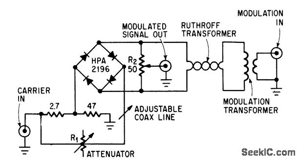
BALANCED MODULATOR DEMODULATOR
This circuit achieves high carrier and modulation suppression by utilizing closely matched diodes. It includes resistor R1 for amplitude adjustment and a coaxial line for phase adjustment. Resistor R2 allows for slight amplitude adjustments.
The described circuit is a diode...
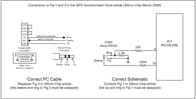
GPS Synchronised Clock
This project replaces the electronics in a standard quartz wall clock with a circuit that uses GPS satellites to obtain precise time.
The proposed project involves the modification of a conventional quartz wall clock by integrating a GPS-based timing circuit. The...
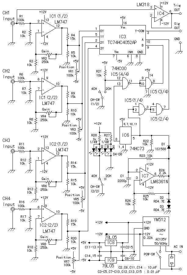
Oscilloscope 4 Channel Adapter
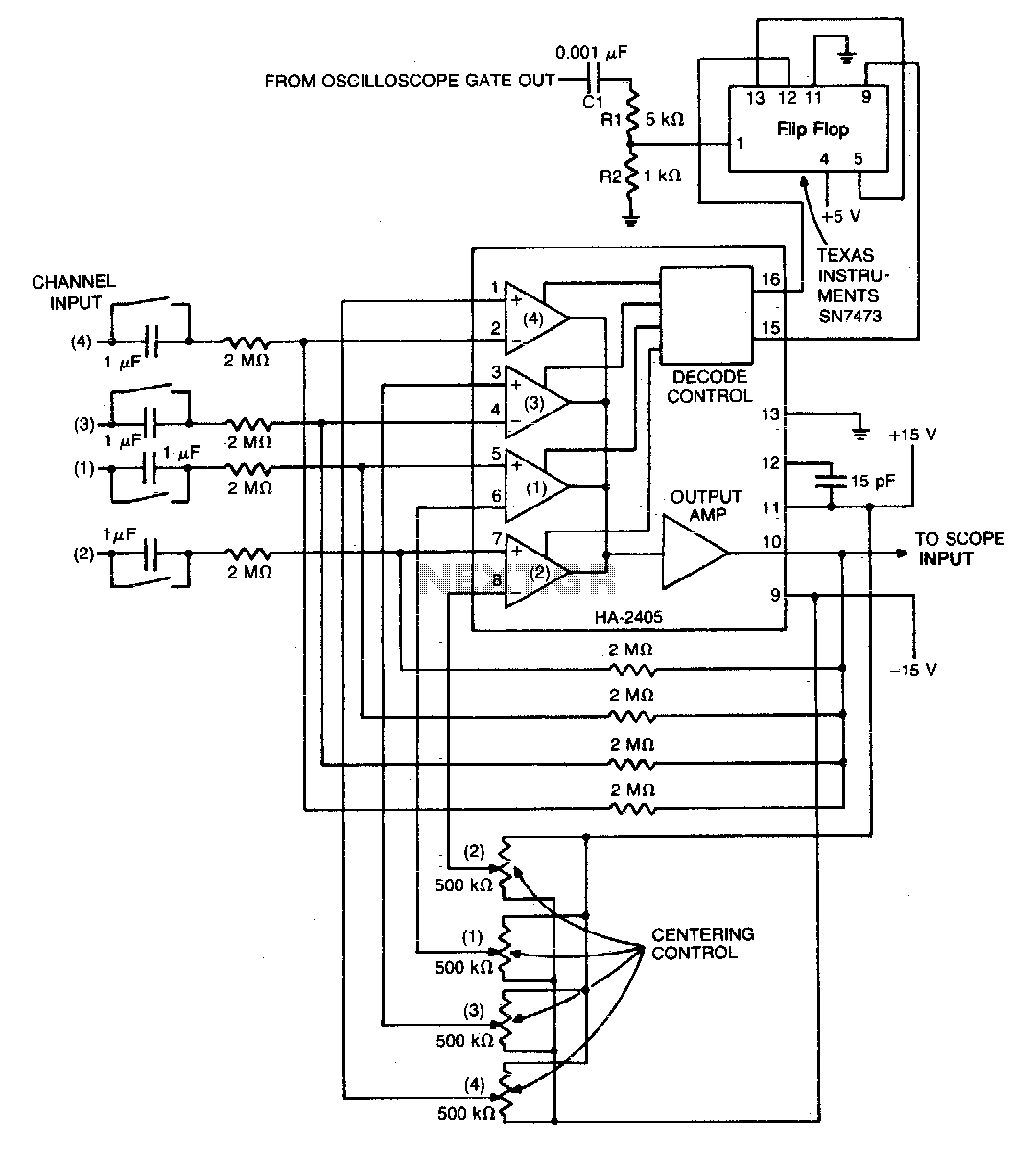
The method goes by the switching method. Making it be possible to see four kinds of the input signals at the same time by switching them at the short period. In addition to the way of introducing here, there is...
Oscilloscope-preamplifier
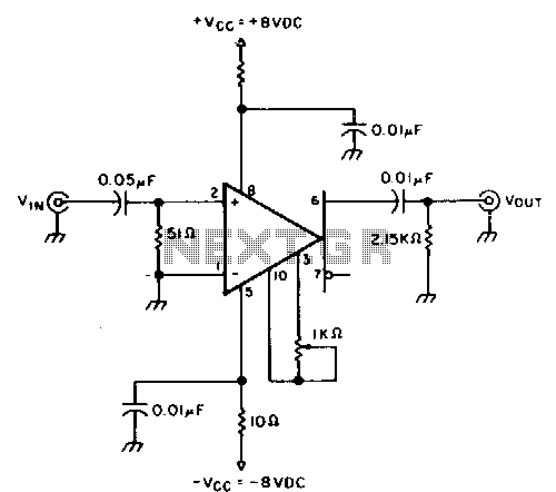
This circuit provides approximately 20 dB of voltage gain with a frequency range from 0.5 to 50 MHz. The low-frequency response of this circuit can be extended by increasing the value of the 0.05 µF capacitor or by removing the...
Oscilloscope converter
The monolithic quad operational amplifier offers a cost-effective solution for enhancing the display capabilities of a standard oscilloscope. Binary inputs control the integrated circuit operational amplifier, while a dual flip-flop divides the oscilloscope's gate output to generate channel selection signals....
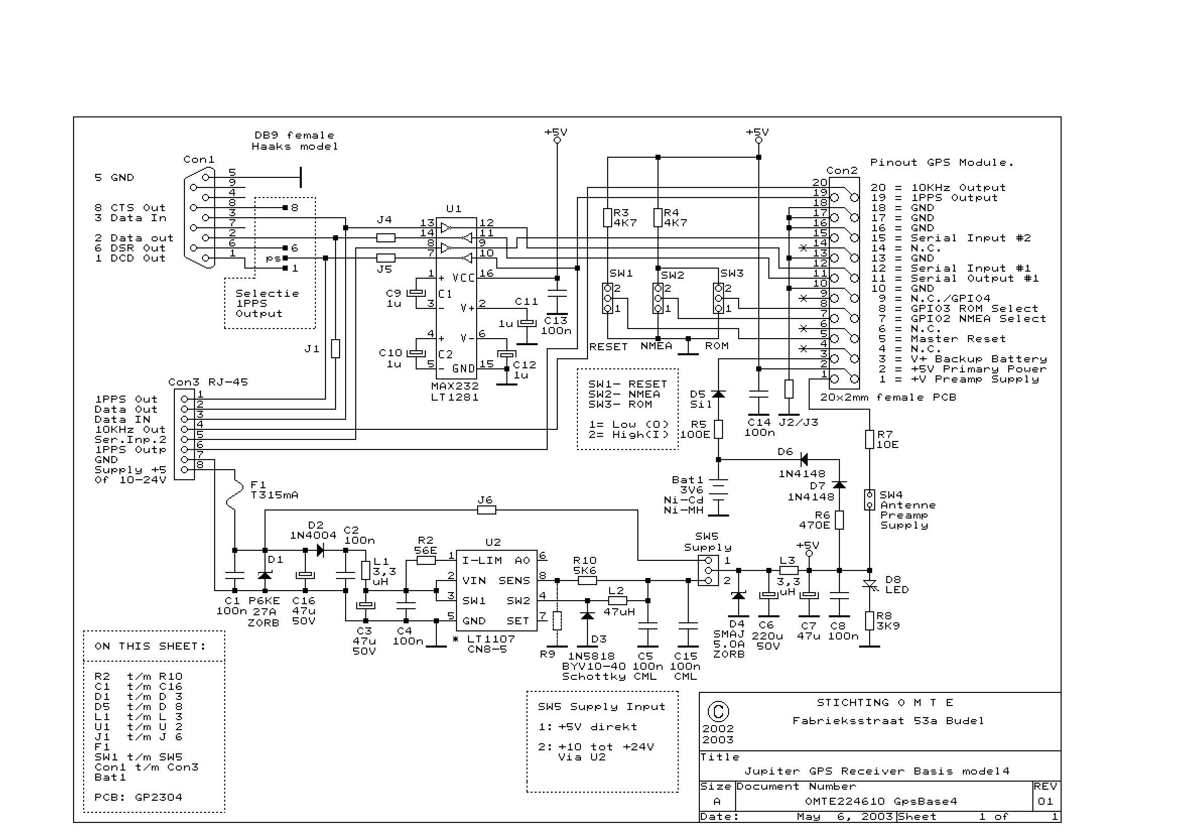
Diagram description GPS support kit
The GPS interface can be fed in 2 ways: with a stabilized 5V supply or with a 10 to 25V unregulated DC supply. In both cases, the power is fed into the RJ45 connector on point 8. Pin 7 is...
Global Positioning System GPS
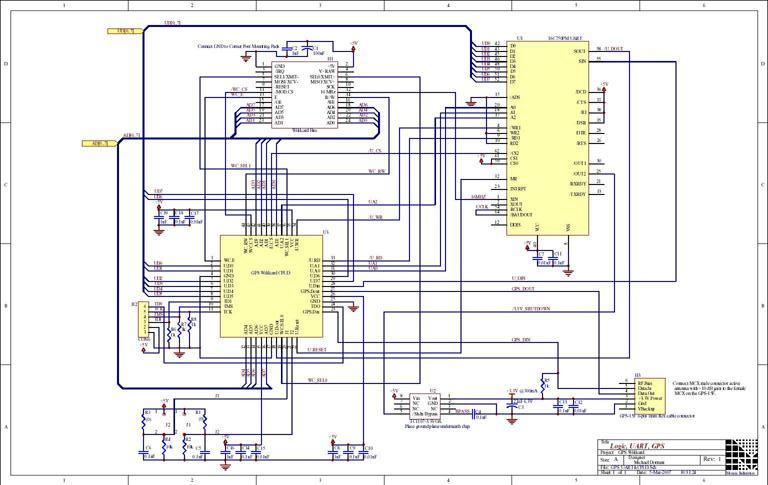
The Global Positioning System (GPS) relies on more than two dozen satellites orbiting the Earth. Each satellite transmits signals that include precise clock information and satellite position data, enabling a GPS receiver to determine its location, speed, and direction. A...
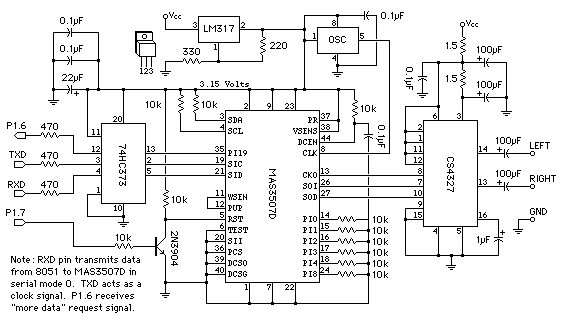
Plans for the Next MP3 Player
This new design has replaced the old one. The design shown on this page is obsolete. The new design has more features, is flash upgradable, is much easier to use, costs less, and is actually available for purchase. It is...
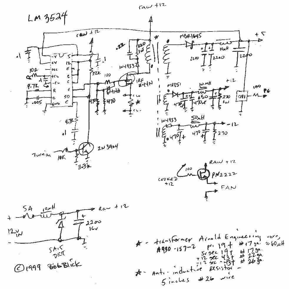
Mobile MP3 Player PC
The CPU is an AMD K5 running 75 MHz. There's 16 meg RAM, and the operating system is Linux (Red Hat 5.2). MPG123 handles the MP3 decoding, and I wrote a control program in Perl.
I built the remote control...