


4 Band Equalizer schematic diagram
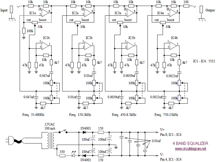
Description: The following diagram illustrates a four-band blaster circuit. This blaster is utilized to enhance sound fidelity, emphasize specific instruments, eliminate unwanted noise, or create entirely new and distinct timbres.
The four-band blaster circuit is designed to manipulate audio signals across four distinct frequency bands. Typically, these bands are categorized into low, mid-low, mid-high, and high frequencies. Each band is processed through a separate equalization stage, allowing for precise control over the amplitude and tonal characteristics of the audio signal.
The circuit generally consists of the following key components:
1. **Input Stage**: This stage receives the audio signal, which can come from various sources such as musical instruments or microphones. It often includes a buffer amplifier to ensure that the input impedance is high enough to prevent signal loss.
2. **Equalization Stages**: Each of the four bands is processed through its own equalizer, which may utilize active or passive components. Active equalizers typically use operational amplifiers (op-amps) to achieve greater control over the gain and bandwidth of each band. The design may include adjustable potentiometers for tuning the gain of each band, allowing users to tailor the sound to their preferences.
3. **Mixing Stage**: After processing, the signals from each band are mixed together. This stage may include additional circuitry to maintain a balanced output level and to prevent distortion.
4. **Output Stage**: The final output stage may include a power amplifier or a simple buffer to drive the output signal to the desired load, such as speakers or recording equipment. This stage ensures that the output maintains fidelity and clarity, preserving the enhancements made during processing.
The four-band blaster circuit is particularly useful in live sound applications and studio settings, where control over frequency response is crucial for achieving high-quality sound. By effectively managing the tonal balance, it allows sound engineers and musicians to craft their desired audio experience, whether for live performances or recorded tracks.The afterward diagram is the four bandage blaster circuit. Blaster is about acclimated to advance the allegiance of sound, to accent assertive instruments, to abolish causeless noises, or to actualize absolutely new and altered timbres
The four-band blaster circuit is designed to manipulate audio signals across four distinct frequency bands. Typically, these bands are categorized into low, mid-low, mid-high, and high frequencies. Each band is processed through a separate equalization stage, allowing for precise control over the amplitude and tonal characteristics of the audio signal.
The circuit generally consists of the following key components:
1. **Input Stage**: This stage receives the audio signal, which can come from various sources such as musical instruments or microphones. It often includes a buffer amplifier to ensure that the input impedance is high enough to prevent signal loss.
2. **Equalization Stages**: Each of the four bands is processed through its own equalizer, which may utilize active or passive components. Active equalizers typically use operational amplifiers (op-amps) to achieve greater control over the gain and bandwidth of each band. The design may include adjustable potentiometers for tuning the gain of each band, allowing users to tailor the sound to their preferences.
3. **Mixing Stage**: After processing, the signals from each band are mixed together. This stage may include additional circuitry to maintain a balanced output level and to prevent distortion.
4. **Output Stage**: The final output stage may include a power amplifier or a simple buffer to drive the output signal to the desired load, such as speakers or recording equipment. This stage ensures that the output maintains fidelity and clarity, preserving the enhancements made during processing.
The four-band blaster circuit is particularly useful in live sound applications and studio settings, where control over frequency response is crucial for achieving high-quality sound. By effectively managing the tonal balance, it allows sound engineers and musicians to craft their desired audio experience, whether for live performances or recorded tracks.The afterward diagram is the four bandage blaster circuit. Blaster is about acclimated to advance the allegiance of sound, to accent assertive instruments, to abolish causeless noises, or to actualize absolutely new and altered timbres
Audio Equalizer Circuit
Designed for communications use, this equalizer circuit utilizes a Mitsubishi M5226P audio equalizer IC to modify frequency response. It operates with a supply voltage ranging from 9 to 20 V. Capacitors C6 through C16 are polyester film capacitors with a...
Ten-band-octave-equalizer
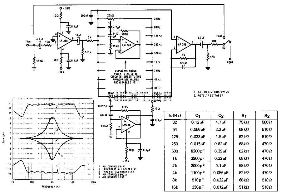
A series of active RF filters using the National LM3481C comprises a ten-band graphic equalizer. C1, C2, R1, and R2 should be at least 10% with 5% preferred tolerances.
The circuit design features a ten-band graphic equalizer that utilizes a series...
4047/4066 audio slicer
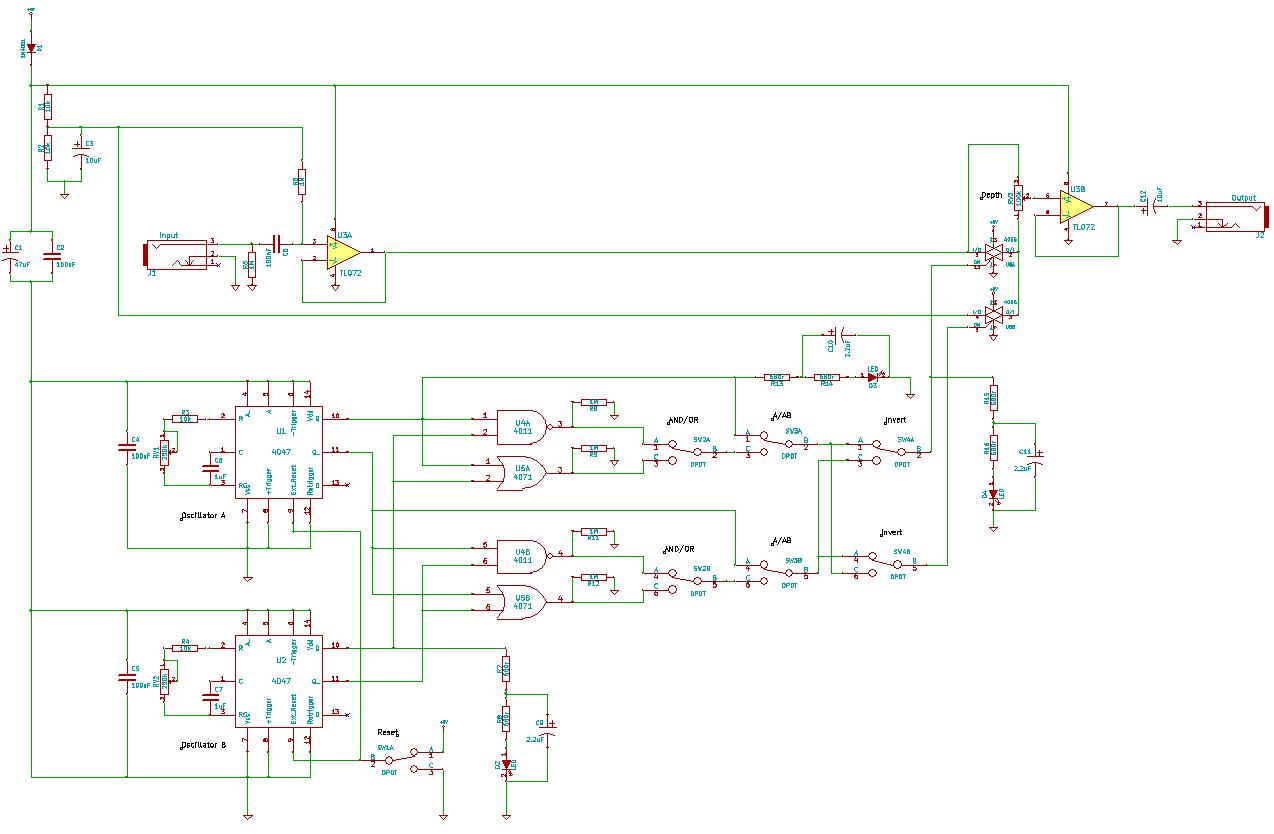
You need to connect pins 1 and 13 of the 4053 to the virtual ground rail (top of C4), not the circuit's 0V rail.
The CD4053 is a triple 2-channel analog multiplexer/demultiplexer integrated circuit, widely used for routing analog signals...
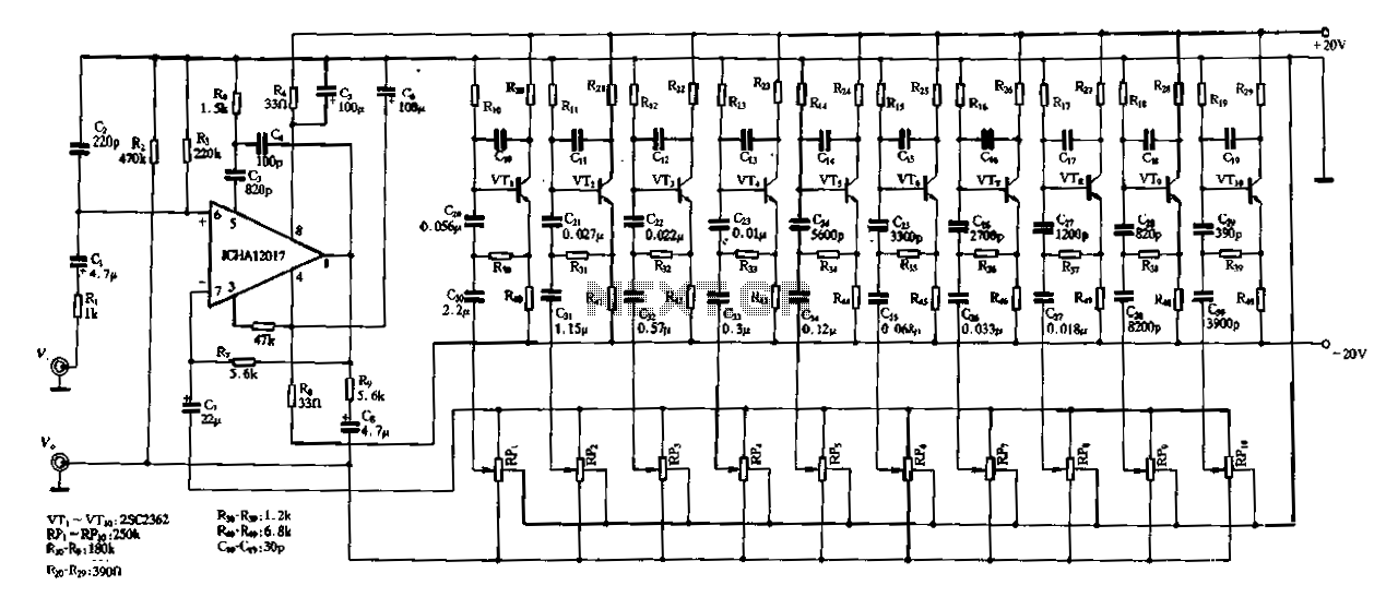
Ten-segment frequency equalizer
Figure 1-97 illustrates a ten-band equalizer circuit with its initial connection. Figure 1C represents the utility voltage amplifier, with R7 functioning similarly to the island depicted in Figure 1-92 R1. Additionally, R2 and the transistors VTr to VTio form the...
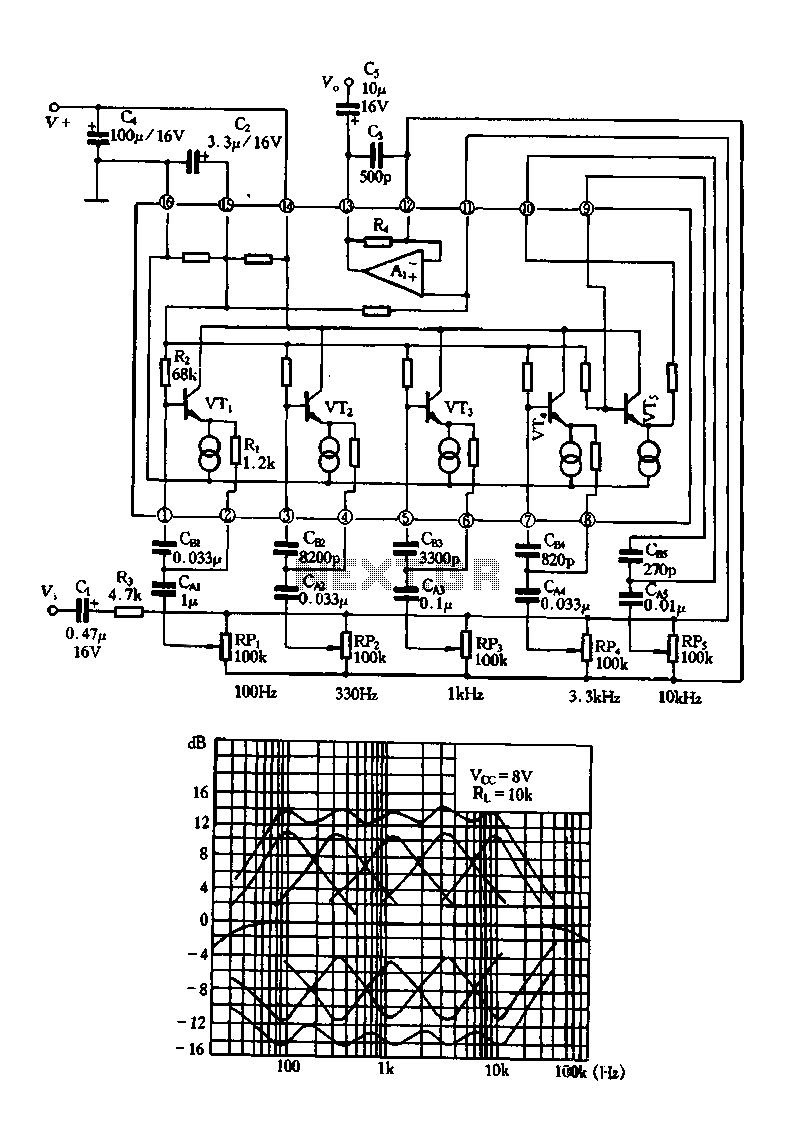
Composition equalizer with TA7796
Figure 1-99 illustrates a five-band equalizer circuit utilizing the TA7796 integrated circuit. This circuit is designed for public electricity voltage amplification and includes analog inductors integrated with transistors. The circuit features a common voltage operational amplifier (op-amp), with VTs and...
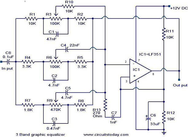
3 Band graphic equalizer circuit
A simple three-band graphic equalizer circuit is constructed using a single op-amp IC, the LF351 (IC1), along with several passive components. The component values in this circuit are not highly critical, allowing for substitutions with nearby values that result in...
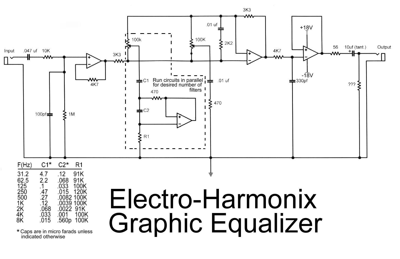
Electro harmonix graphic equalizer circuit
This is the diagram of the Electro-Harmonix graphic equalizer. The number of channels can be specified according to requirements by paralleling the components: C1, C2, R1, an operational amplifier, potentiometer, and a 470-ohm resistor. The frequency to be boosted is...
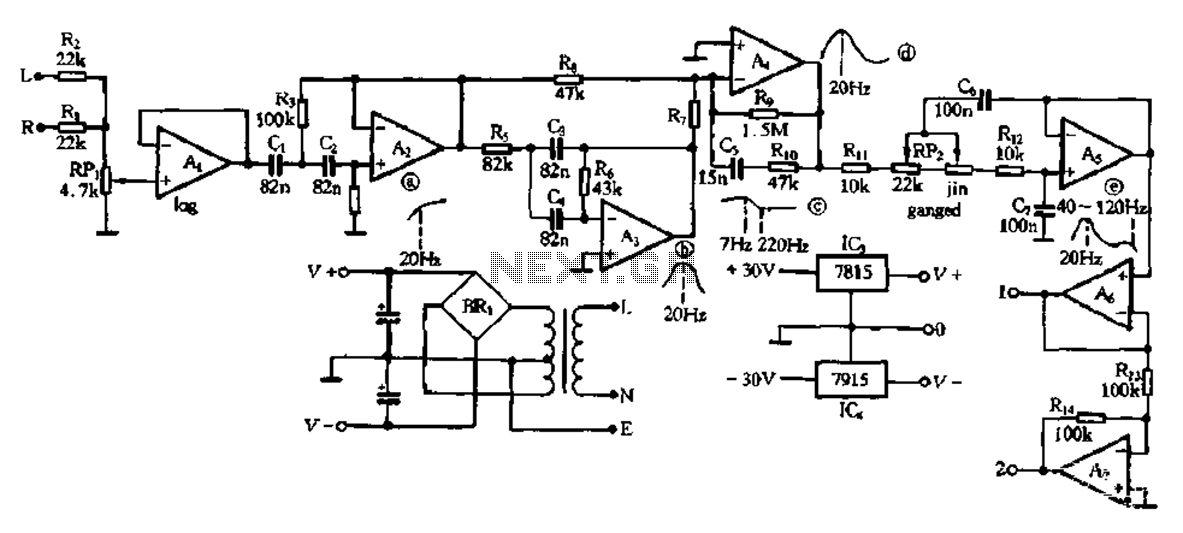
Electronic type bass equalization circuit
This electronic bass equalizer circuit utilizes two quad operational amplifiers, specifically the TL084 high-speed operational amplifier. The circuit includes left and right channels that are mixed through resistors R1 and R2, and features a total bass level adjustment potentiometer designed...
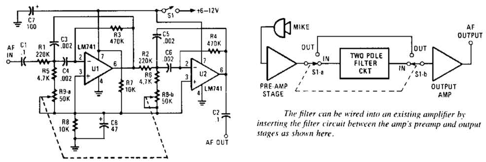
Build a Variable-Frequency Audio Band pass FilterCircuit
This variable-frequency audio bandpass filter is constructed using two 741 operational amplifiers connected in cascade. The two 741 op amps are configured as identical RC active filters and are cascaded to enhance selectivity. The filter's tuning range spans from 500...