


Asymmetric third order Butterworth active crossover network circuit diagram
#active crossover
#Butterworth filter
#third order filter
#audio processing
#signal filtering
#frequency separation
#audio circuit
#sound engineering
#filter design
#stereo systems
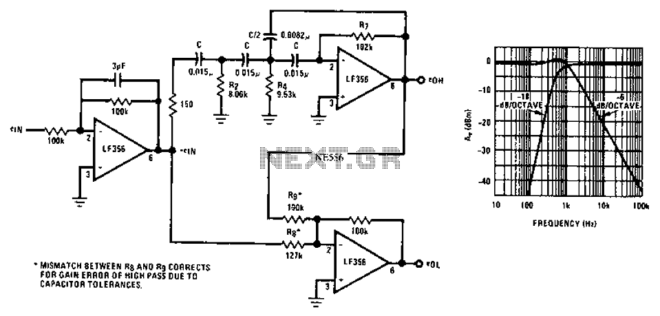
Description: Asymmetric third-order Butterworth active crossover network circuit diagram.
The asymmetric third-order Butterworth active crossover network is a sophisticated circuit designed to split an audio signal into two separate frequency bands, typically for use in multi-way speaker systems. This type of crossover employs active components, such as operational amplifiers (op-amps), to achieve a precise frequency response and a smooth transition between the low-pass and high-pass outputs.
In this circuit, the Butterworth filter design is chosen for its maximally flat frequency response within the passband, ensuring minimal signal distortion. The third-order configuration provides a steeper roll-off rate of 18 dB per octave, which enhances the separation between the audio bands, thereby improving overall sound quality.
The circuit typically consists of two main sections: the low-pass filter and the high-pass filter. Each section utilizes multiple op-amps configured in a feedback arrangement to achieve the desired filter characteristics. The cutoff frequency, where the signal begins to attenuate, is determined by the values of resistors and capacitors used in the circuit.
To implement an asymmetric design, the component values can be adjusted to create differing slopes or cutoff frequencies for the low-pass and high-pass sections, allowing for tailored audio performance based on specific speaker characteristics or user preferences.
Power supply considerations are essential for active crossover networks; typically, a dual power supply is employed to provide the necessary positive and negative voltage rails for the op-amps. Additionally, careful attention must be paid to grounding and layout to minimize noise and interference, ensuring high-fidelity audio output.
In summary, the asymmetric third-order Butterworth active crossover network is an advanced circuit that provides effective frequency separation and high-quality audio performance, making it a valuable component in professional audio systems. Asymmetric third order Butterworth active crossover network circuit diagram as follows:
The asymmetric third-order Butterworth active crossover network is a sophisticated circuit designed to split an audio signal into two separate frequency bands, typically for use in multi-way speaker systems. This type of crossover employs active components, such as operational amplifiers (op-amps), to achieve a precise frequency response and a smooth transition between the low-pass and high-pass outputs.
In this circuit, the Butterworth filter design is chosen for its maximally flat frequency response within the passband, ensuring minimal signal distortion. The third-order configuration provides a steeper roll-off rate of 18 dB per octave, which enhances the separation between the audio bands, thereby improving overall sound quality.
The circuit typically consists of two main sections: the low-pass filter and the high-pass filter. Each section utilizes multiple op-amps configured in a feedback arrangement to achieve the desired filter characteristics. The cutoff frequency, where the signal begins to attenuate, is determined by the values of resistors and capacitors used in the circuit.
To implement an asymmetric design, the component values can be adjusted to create differing slopes or cutoff frequencies for the low-pass and high-pass sections, allowing for tailored audio performance based on specific speaker characteristics or user preferences.
Power supply considerations are essential for active crossover networks; typically, a dual power supply is employed to provide the necessary positive and negative voltage rails for the op-amps. Additionally, careful attention must be paid to grounding and layout to minimize noise and interference, ensuring high-fidelity audio output.
In summary, the asymmetric third-order Butterworth active crossover network is an advanced circuit that provides effective frequency separation and high-quality audio performance, making it a valuable component in professional audio systems. Asymmetric third order Butterworth active crossover network circuit diagram as follows:
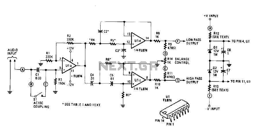
Active crossover circuit with TL074
An audio source, such as a mixer, preamp, EQ, or recorder, is connected to the input of the Electronic Crossover Circuit. The signal can be either AC or coupled, depending on the setting of switch 51, which controls the non-inverting...
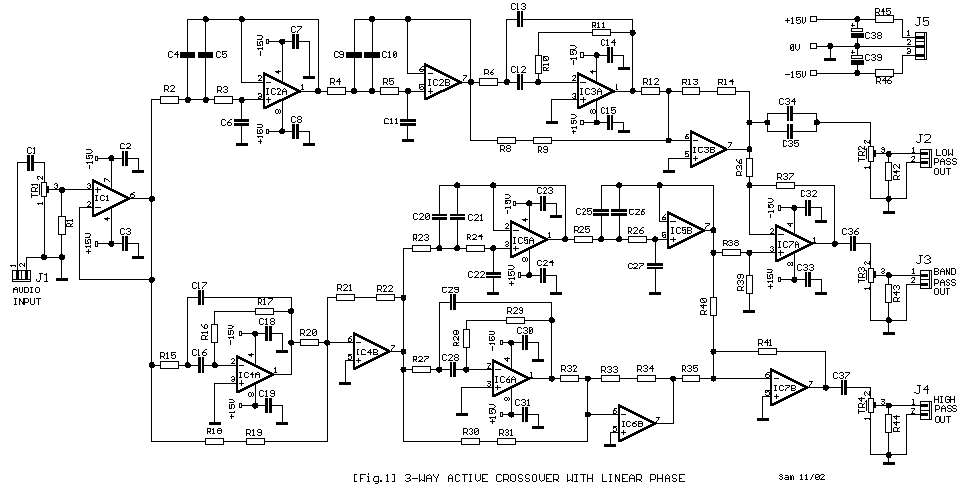
Active Crossover
The problems that exist in common crossover networks are known. The low-pass filter causes delay in the signal. On the contrary, the high-pass filter causes a pre-ahead in the signal that it goes through from this. So, the cross-frequency creates...
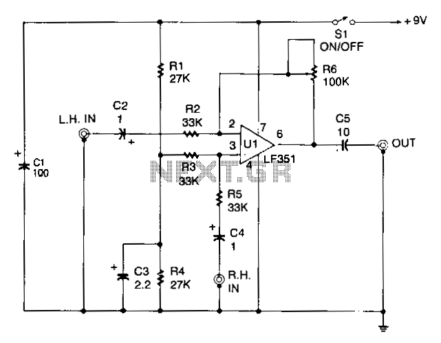
Central-image-canceller
The circuit is designed to eliminate the vocal portion of an audio signal while preserving the instrumental portion. It achieves this by mixing two channels that are 180° out of phase, allowing the signals that create the center-stereo image to...
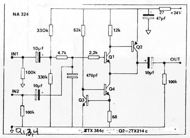
Better-Sounding Active Crossovers
Can anyone explain the function of the four transistors located on the right-hand side of each of McBride's schematics?
The presence of four transistors on the right-hand side of McBride's schematics typically indicates a specific function related to signal amplification, switching,...
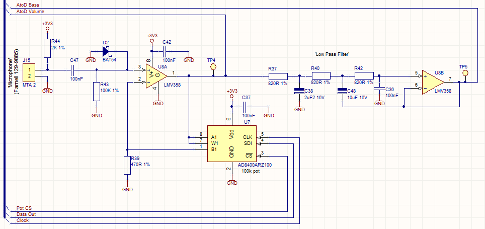
Audio Beat Detect ?« Electronic Product Design
This circuit employs a digital potentiometer to enable the microcontroller to automatically adjust the circuit's gain according to the ambient audio volume. However, a standard potentiometer can be used if automatic adjustment is unnecessary. The low-pass filter design is based...
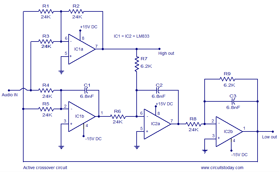
Active Crossover Circuit-Schematic-Design and Diagram
Active crossover circuit design, circuit diagram, schematic, DIY active crossover circuit, HiFi audio crossover, 2-way crossover circuit using LM833.
The active crossover circuit is an essential component in high-fidelity audio systems, allowing for the separation of audio signals into different frequency...
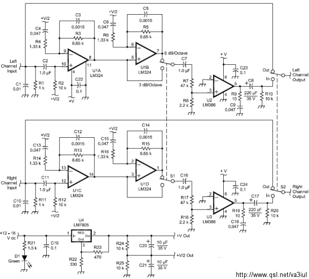
ARRL Handbook Audio Intelligibility Enhancer
Assistance is sought for building the N4GG audio intelligibility enhancer project as detailed in the ARRL Handbook. A circuit board has been ordered from Far Circuits, but there are difficulties in sourcing the necessary components. Attempts have been made to...
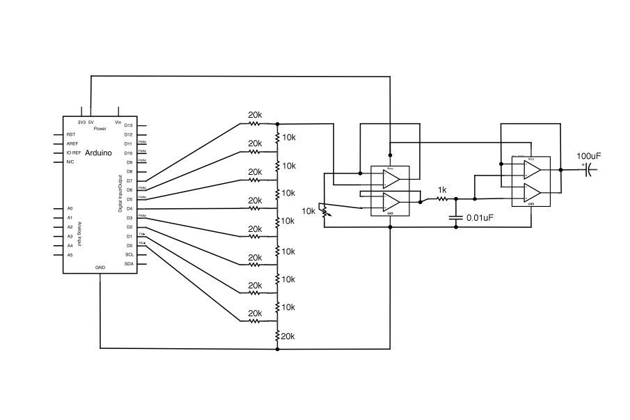
Arduino Vocal Effects Box
This Arduino-powered vocal effects box pitch shifts and distorts incoming audio signals to produce a wide variety of vocal effects. This project is an experiment with real-time digital signal processing using Arduino. It samples an incoming microphone signal at a...
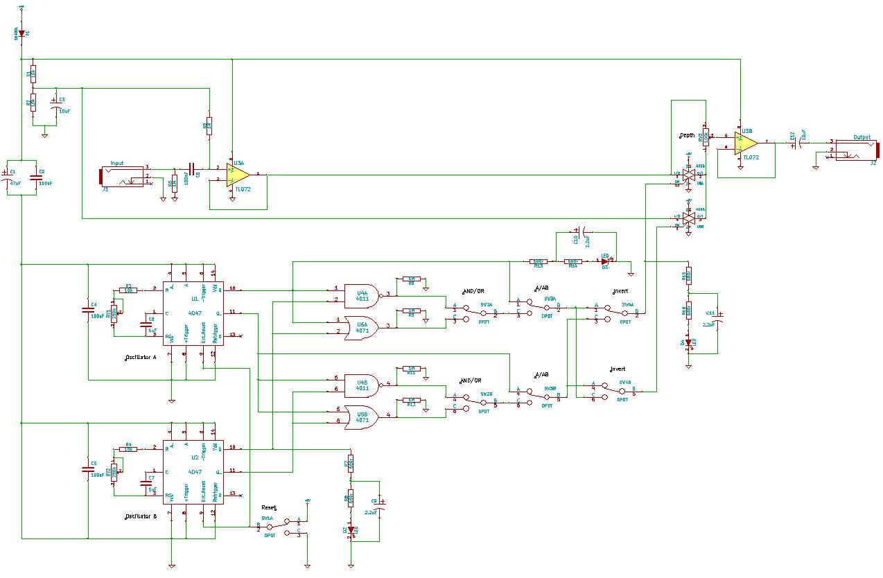
4047/4066 audio slicer
You need to connect pins 1 and 13 of the 4053 to the virtual ground rail (top of C4), not the circuit's 0V rail.
The CD4053 is a triple 2-channel analog multiplexer/demultiplexer integrated circuit, widely used for routing analog signals...