


Guitar noise circuit diagram
#guitar
#noise
#distortion
#operational amplifier
#741
#gain
#audio circuit
#signal processing
#amplifier
#sound effect
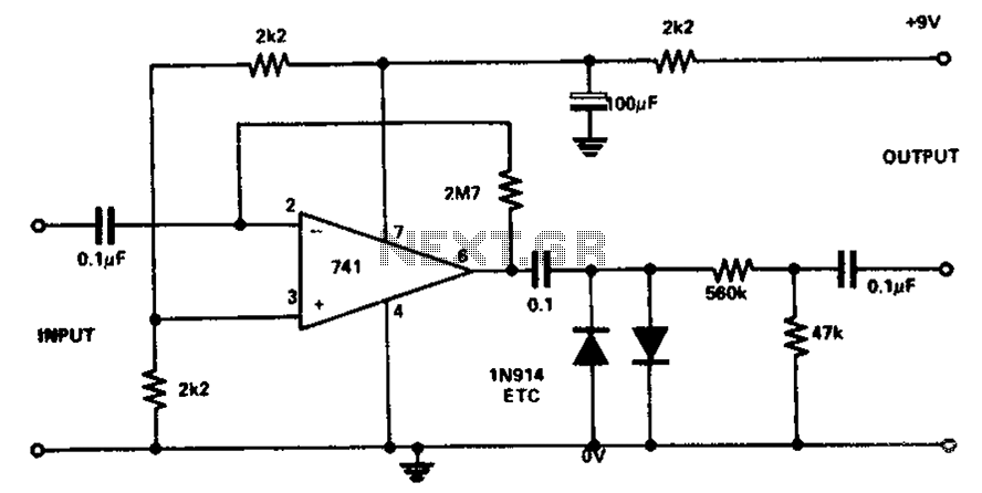
Description: The circuit utilizes the 741 operational amplifier, which has a maximum gain of 20,000. However, the design achieves a gain of 2.7 million, resulting in output distortion. This distortion is attributed to noise effects. Two clamping diodes are employed to limit the output, while two additional diodes influence the gain. The circuit configuration is designed to produce a new sound while also preserving the original sound.
The described circuit leverages the operational amplifier (op-amp) model 741, known for its versatility in various applications. The maximum theoretical gain of the 741 is 20,000; however, in this design, the op-amp is configured to achieve an extraordinary gain of 2.7 million. This excessive gain can lead to significant output distortion, primarily due to noise interference, which is common in high-gain amplifier circuits.
To mitigate the distortion effects, the circuit incorporates two clamping diodes. These diodes function to prevent the output voltage from exceeding certain levels, thereby reducing the likelihood of clipping and maintaining signal integrity. The clamping action helps to stabilize the output, ensuring that the amplifier operates within a linear range.
Additionally, two other diodes are included in the design to influence the gain characteristics of the circuit. These diodes play a crucial role in shaping the frequency response and enhancing the overall performance of the amplifier. The combined effect of the clamping and gain-modifying diodes results in a circuit capable of generating a new sound profile while still preserving the nuances of the original audio signal.
The circuit's design is particularly useful in audio applications where maintaining sound quality is paramount. It can be employed in various audio processing tasks, such as effects units or sound synthesis, where both the manipulation of sound and fidelity to the original source are desired. Careful consideration of component selection and circuit layout will further enhance performance and minimize unwanted artifacts in the output. Circuit Description: The maximum gain circuit 741 to 20000, but the design of the circuit while filling a gain of 2.7 million, and then causes the output distortion. This disto rtion caused by noise effects. Two clamping diodes to reduce output low, while the two diodes that points multiplier impact becomes low. Since the sandwich will produce a new sound, the circuit can also be used to maintain the original sound.
The described circuit leverages the operational amplifier (op-amp) model 741, known for its versatility in various applications. The maximum theoretical gain of the 741 is 20,000; however, in this design, the op-amp is configured to achieve an extraordinary gain of 2.7 million. This excessive gain can lead to significant output distortion, primarily due to noise interference, which is common in high-gain amplifier circuits.
To mitigate the distortion effects, the circuit incorporates two clamping diodes. These diodes function to prevent the output voltage from exceeding certain levels, thereby reducing the likelihood of clipping and maintaining signal integrity. The clamping action helps to stabilize the output, ensuring that the amplifier operates within a linear range.
Additionally, two other diodes are included in the design to influence the gain characteristics of the circuit. These diodes play a crucial role in shaping the frequency response and enhancing the overall performance of the amplifier. The combined effect of the clamping and gain-modifying diodes results in a circuit capable of generating a new sound profile while still preserving the nuances of the original audio signal.
The circuit's design is particularly useful in audio applications where maintaining sound quality is paramount. It can be employed in various audio processing tasks, such as effects units or sound synthesis, where both the manipulation of sound and fidelity to the original source are desired. Careful consideration of component selection and circuit layout will further enhance performance and minimize unwanted artifacts in the output. Circuit Description: The maximum gain circuit 741 to 20000, but the design of the circuit while filling a gain of 2.7 million, and then causes the output distortion. This disto rtion caused by noise effects. Two clamping diodes to reduce output low, while the two diodes that points multiplier impact becomes low. Since the sandwich will produce a new sound, the circuit can also be used to maintain the original sound.
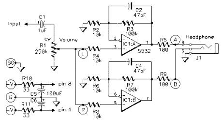
headphone monitor amp
This simple amplifier is designed to add a headphone jack to equipment that does not have this feature. The Headphone Buffer circuit board is compact (1.2" x 1.4"), allowing it to fit into even the smallest spaces, and its low...
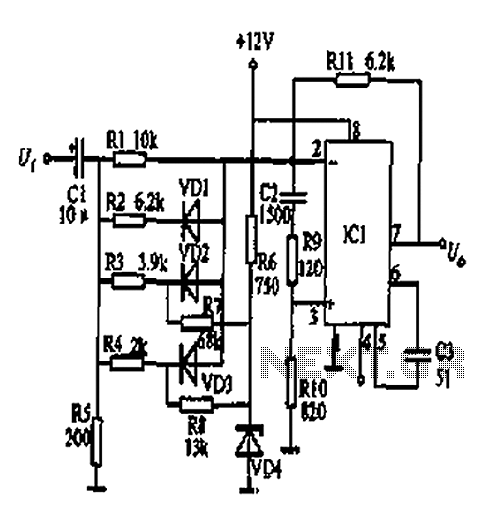
Square transform circuit diagram
At the input of the operational amplifier, a resistor-diode network can be constructed to create a square-law function conversion circuit. This resistor-diode network acts as a voltage divider, where the input voltage variations lead to different partial pressures. The three...
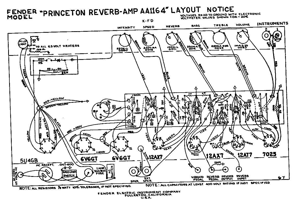
69 SFPR Schematic Telecaster Guitar
A 1969 Princeton Reverb amplifier is identified as utilizing the AA764 circuit design. Various online resources provide schematics for Fender amplifiers.
The Princeton Reverb amplifier, particularly the model from 1969, is renowned for its warm tone and versatile sound characteristics, making...
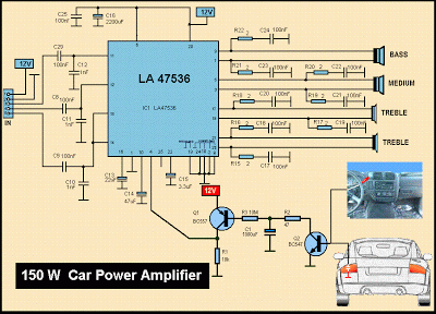
Schematic MP3 Car Audio Power AmplifierCircuits
This is a diagram of a car audio active loudspeaker utilizing the LF353 operational amplifier from National Semiconductor. For optimal performance, the NE5532 is recommended to split the audio signal into three frequency bands using an active filter. The SANYO...
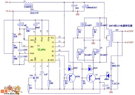
Precision current sink sourcel
An operational amplifier circuit can provide a constant voltage source with a high amplification factor and substantial load current. Even with significant variations in circuit parameters, the output voltage maintains high precision. The output current limit is managed by transistors...
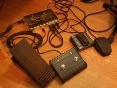
Guitar Loop with Arduino
Build a Guitar Looper with an Arduino board. Here is how to produce a pedalboard for electric guitar. The idea is to connect pedals to the Arduino and to use them to control a software of sound processing in Pure...
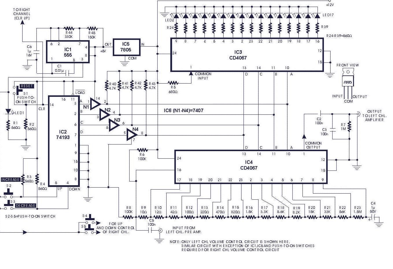
audio circuits 20
The gain of the single-stage virtual earth amplifier IC1 is determined by the drain-source resistance of the field-effect transistor (FET). Resistors R1, R2, and R3 linearize the FET's voltage-current characteristic. A control voltage is derived from the output signal using...
Bird Feeder Monitor Circuit
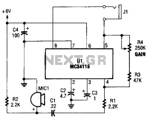
The first amplifier circuit is a bird phone. In this circuit, the electret microphone (MIC1) is mounted in the neck of a large plastic funnel. The amplifier, built around an MC34119, is then placed outside of the funnel with the...
lowvoltage ac voltmeter
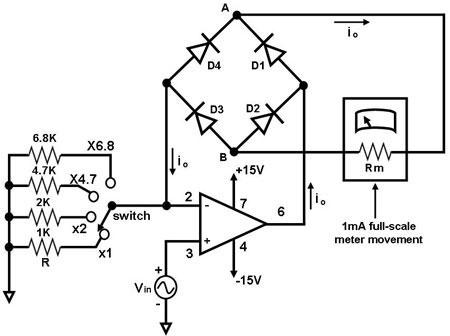
The primary component of this circuit is an operational amplifier (such as the 741 or 351), configured as an amplifier with a feedback circuit that consists of a diode bridge full-wave rectifier. An ammeter is connected to the rectifier circuit,...