


Guitar OmniDrive effect
#distortion pedal
#analogue modelling
#pre-amplifier
#treble boost
#low pass filter
#full wave rectifier
#clipping stage
#guitar effect
#variable gain
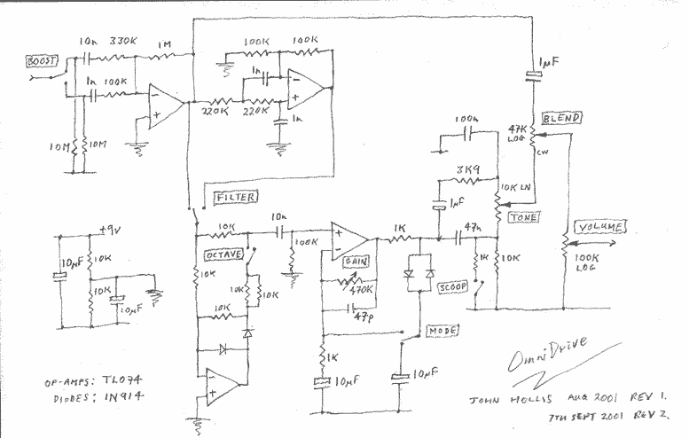
Description: This is a versatile distortion pedal. Think of it as analogue modelling, using analogue circuitry to model a wide range of analogue distortion devices. It includes the main elements found in the majority of distortion boxes. The unit comprises four sections: A pre-amplifier with switchable treble boost. A switchable low pass filter. A switchable full wave rectifier for octave-up effects. A clipping stage with variable gain and two clipping modes. More: These stages are combined with level and tone controls to allow emulation of most of the multi-stage overdrive and fuzz units. The rotary controls are drive, tone, blend and volume. The switches are treble boost, low-pass filter, octave up and distortion mode. I have also added an optional scoop switch to the tone control circuit. This cuts the mid-range and should be popular with death metal noise vandals. I suggest mounting the clipping diodes via a 3.5mm miniature break jack. That way you can insert little plugs with germanium diodes or asymmetric diodes or whatever in them.
The distortion pedal described operates using a series of interconnected analog circuits that allow for a wide range of tonal shaping and distortion effects. The pre-amplifier section is designed to amplify the input signal while offering a switchable treble boost, enhancing higher frequencies for a brighter sound. This is particularly useful for achieving clarity in distorted tones.
The switchable low-pass filter serves to attenuate higher frequencies, allowing for a warmer, smoother distortion that can be tailored to the user's preference. This feature is crucial for creating a variety of tonal characteristics, from classic rock sounds to heavier genres.
The inclusion of a switchable full-wave rectifier enables octave-up effects, which can add harmonic richness to the signal. This section is particularly valuable for creating unique sound textures that stand out in a mix.
The clipping stage is a vital component of the distortion pedal, featuring variable gain control and two distinct clipping modes. This allows the user to select between different distortion characteristics, whether they prefer a smooth overdrive or a more aggressive fuzz tone.
The rotary controls for drive, tone, blend, and volume provide intuitive user interaction, allowing for precise adjustments to the overall sound. The drive control adjusts the amount of distortion applied to the signal, while the tone control shapes the overall frequency response. The blend control allows for mixing between the clean and distorted signals, enabling a more dynamic range of sound. The volume control sets the output level of the pedal.
The additional scoop switch modifies the tone control circuit by cutting mid-range frequencies, catering to specific styles such as death metal, where a scooped mid-range is often desired.
For versatility in sound design, the suggestion to mount the clipping diodes via a 3.5mm miniature break jack allows users to experiment with different diode types, such as germanium or asymmetric diodes. This feature enhances the pedal's adaptability, enabling users to customize their distortion characteristics further.
Overall, the described distortion pedal combines essential elements of analog circuitry with user-friendly controls, making it suitable for a wide range of musical styles and preferences.This is a versatile distortion pedal. Think of it as analogue modelling, using analogue circuitry to model a wide range of analogue distortion devices. It includes the main elements found in the majority of distortion boxes. The unit comprises four sections: A pre-amplifier with switchable treble boost. A switchable low pass filter. A switchable full wave rectifier for octave-up effects. A clipping stage with variable gain and two clipping modes. These stages are combined with level and tone controls to allow emulation of most of the multi-stage overdrive and fuzz units. The rotary controls are drive, tone, blend and volume. The switches are treble boost, low-pass filter, octave up and distortion mode. I have also added an optional scoop switch to the tone control circuit. This cuts the mid-range and should be popular with death metal noise vandals. I suggest mounting the clipping diodes via a 3.5mm miniature break jack. That way you can insert little plugs with germanium diodes or asymmetric diodes or whatever in them.
The distortion pedal described operates using a series of interconnected analog circuits that allow for a wide range of tonal shaping and distortion effects. The pre-amplifier section is designed to amplify the input signal while offering a switchable treble boost, enhancing higher frequencies for a brighter sound. This is particularly useful for achieving clarity in distorted tones.
The switchable low-pass filter serves to attenuate higher frequencies, allowing for a warmer, smoother distortion that can be tailored to the user's preference. This feature is crucial for creating a variety of tonal characteristics, from classic rock sounds to heavier genres.
The inclusion of a switchable full-wave rectifier enables octave-up effects, which can add harmonic richness to the signal. This section is particularly valuable for creating unique sound textures that stand out in a mix.
The clipping stage is a vital component of the distortion pedal, featuring variable gain control and two distinct clipping modes. This allows the user to select between different distortion characteristics, whether they prefer a smooth overdrive or a more aggressive fuzz tone.
The rotary controls for drive, tone, blend, and volume provide intuitive user interaction, allowing for precise adjustments to the overall sound. The drive control adjusts the amount of distortion applied to the signal, while the tone control shapes the overall frequency response. The blend control allows for mixing between the clean and distorted signals, enabling a more dynamic range of sound. The volume control sets the output level of the pedal.
The additional scoop switch modifies the tone control circuit by cutting mid-range frequencies, catering to specific styles such as death metal, where a scooped mid-range is often desired.
For versatility in sound design, the suggestion to mount the clipping diodes via a 3.5mm miniature break jack allows users to experiment with different diode types, such as germanium or asymmetric diodes. This feature enhances the pedal's adaptability, enabling users to customize their distortion characteristics further.
Overall, the described distortion pedal combines essential elements of analog circuitry with user-friendly controls, making it suitable for a wide range of musical styles and preferences.This is a versatile distortion pedal. Think of it as analogue modelling, using analogue circuitry to model a wide range of analogue distortion devices. It includes the main elements found in the majority of distortion boxes. The unit comprises four sections: A pre-amplifier with switchable treble boost. A switchable low pass filter. A switchable full wave rectifier for octave-up effects. A clipping stage with variable gain and two clipping modes. These stages are combined with level and tone controls to allow emulation of most of the multi-stage overdrive and fuzz units. The rotary controls are drive, tone, blend and volume. The switches are treble boost, low-pass filter, octave up and distortion mode. I have also added an optional scoop switch to the tone control circuit. This cuts the mid-range and should be popular with death metal noise vandals. I suggest mounting the clipping diodes via a 3.5mm miniature break jack. That way you can insert little plugs with germanium diodes or asymmetric diodes or whatever in them.
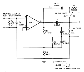
Circuit of RIIA phono pre-amplifier op-27
The circuit contributes 3.2 nV/√Hz of voltage noise and 0.45 pA/√Hz of current noise. To minimize noise from other sources, resistor R3 is configured to 100 ohms, resulting in an additional voltage noise of only 1.3 nV/√Hz. Resistors R1, R2,...
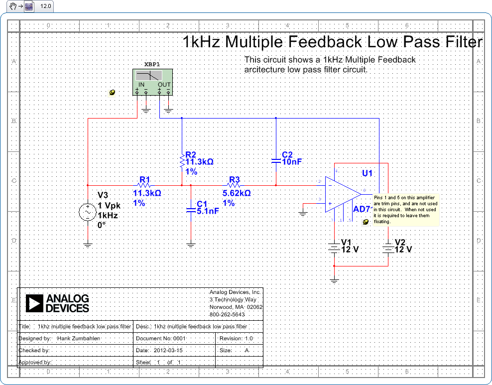
1khz multiple feedback low pass filter circuit
Pins 1 and 5 on this amplifier are trim pins and are not utilized in the circuit. When not in use, it is necessary to leave them floating.
In electronic amplifier circuits, trim pins are often included for calibration or adjustment...
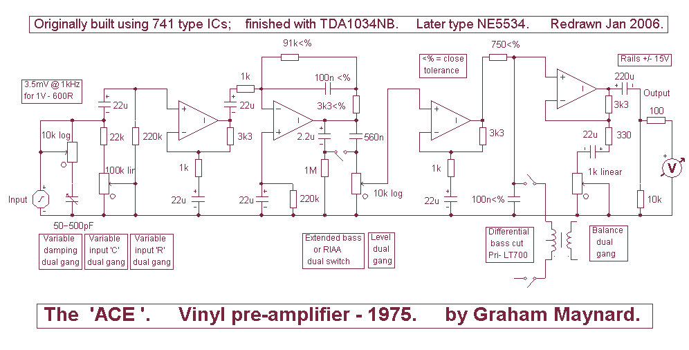
Vinyl Pre-Amplifier
Many designers assert that NFB loop controlled amplifiers are inferior because they degrade the sound. However, it's worth considering what these individuals believe they are actually listening to. The reality is that most vinyl waveforms and CD pits, as part...
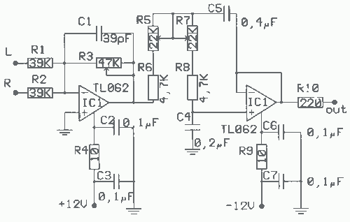
Low pass filter for Subwoofer Circuit
The application that we propose is a simple filter that limits the acoustic region (20-20000Hz) to the region 20-100Hz. With the manufacture proposed, an active filter can be created to drive a loudspeaker for very low frequencies. This allows for...
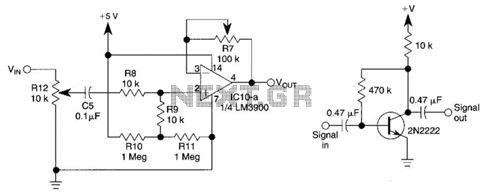
Variable Gain Amplifier Circuit
This circuit utilizes one-quarter of an LM3900 to create a simple variable-gain front end for an oscilloscope. R7 serves as the gain control. Additionally, a basic preamplifier is included for applications requiring more than 10X gain.
The circuit employs the LM3900,...
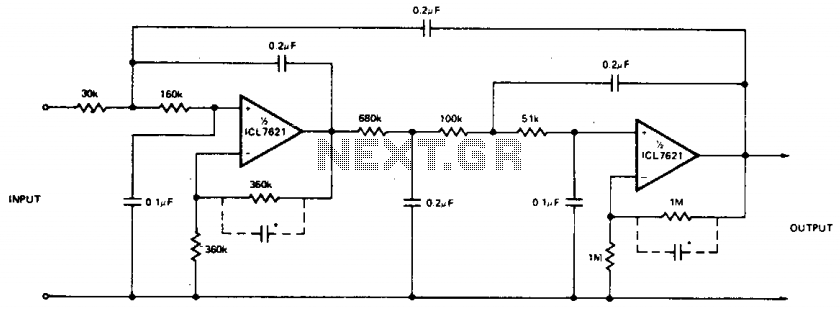
Multiple feedback low pass filter
The low bias currents allow for the utilization of high resistance and low capacitance values, facilitating a low frequency cutoff at fc = 10 Hz, with an AVCL of 4 and a passband ripple of 0.1 dB. Additionally, small capacitors...
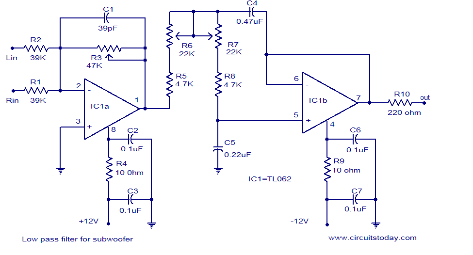
Low pass filter for subwoofer
Several low-pass filter circuits for subwoofers are presented here, and this is another example. The circuit is based on the TL062 op-amp from ST Microelectronics. The TL062 is a dual high-input impedance J-FET op-amp that exhibits very low power consumption...
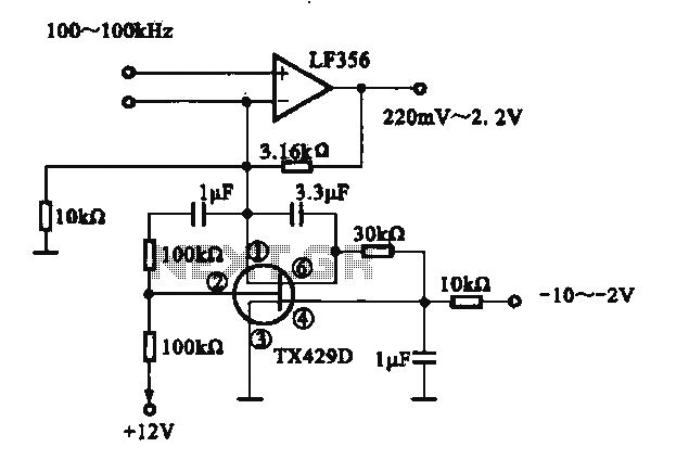
Variable gain amplifier circuit
A variable gain amplifier is presented. This circuit adjusts the output signal amplitude based on the input signal. The core component is an operational amplifier configured with a negative feedback circuit. By varying the feedback amount, the gain of the...
gcr
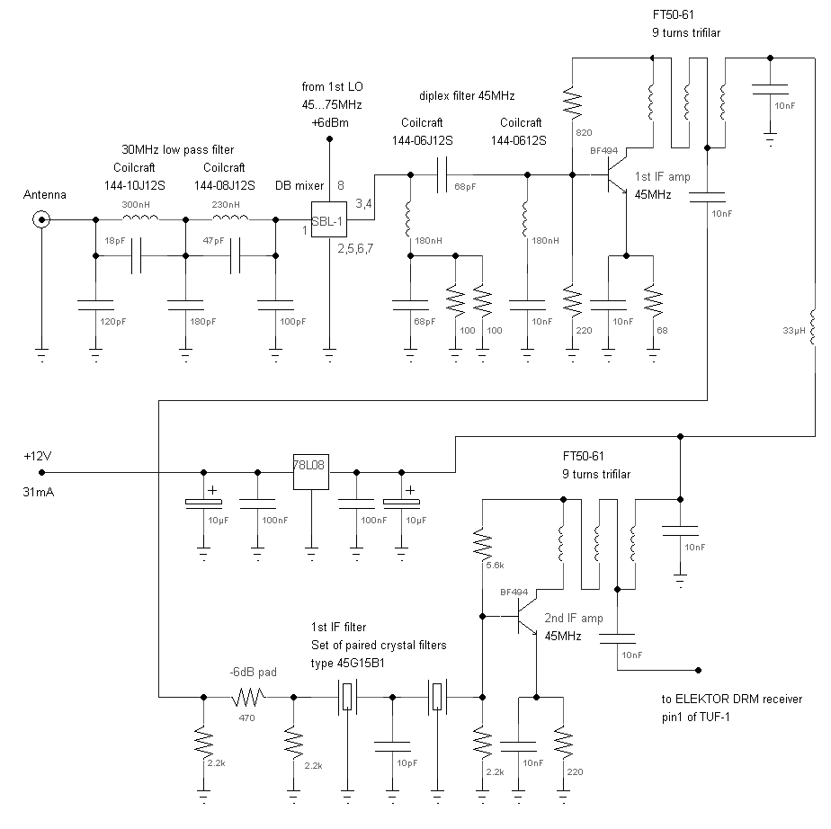
A 5-pole elliptic low pass filter (impedance: 50 Ohm, -6 dB cutoff frequency 33 MHz) connects the antenna signal to the diode ring mixer, a traditional SBL-1, which performs well even below 500 kHz. A high pass/low pass diplexing filter...